
BOAT MAINTENANCE · ELECTRICAL SYSTEMS
Boat Electrical System Explained: Batteries, Alternator, Generator, 12V, 24V & 230V Wiring
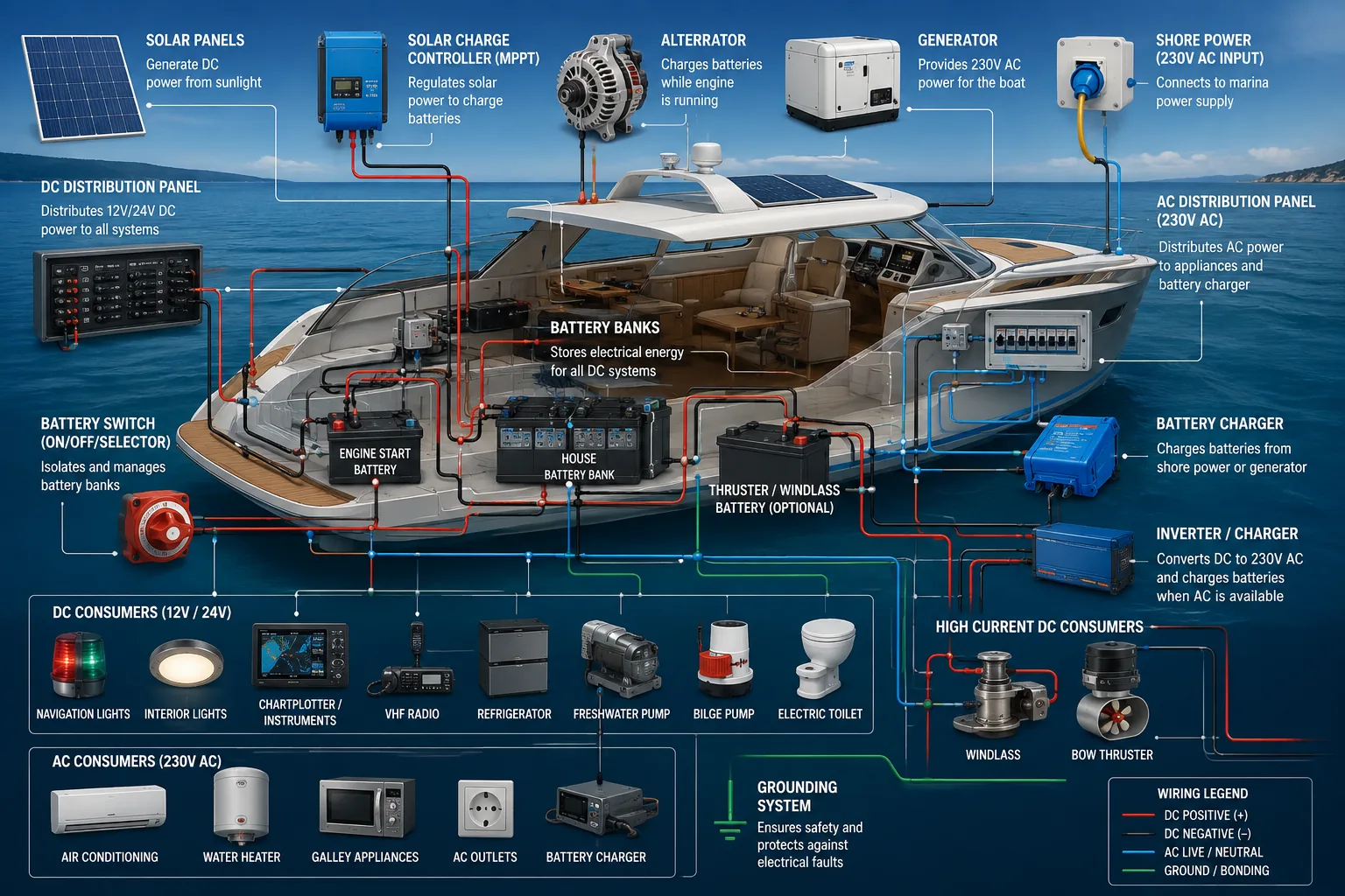
A modern yacht may contain several electrical systems operating at the same time: 12V or 24V DC supplied by batteries, 230V AC supplied by shore power or a generator, battery chargers, alternators, solar controllers, inverters and dozens of electrical consumers ranging from navigation instruments to powerful bow thrusters.
Understanding where the electricity comes from, how it is distributed and what happens when a component fails can make troubleshooting much easier and can prevent serious electrical damage or fire.
1. The Complete Electrical System
The easiest way to understand a boat electrical installation is to divide it into energy sources, energy storage, distribution and consumers.
ENERGY SOURCES
│
├── Shore power 230V AC
├── Generator 230V AC
├── Engine alternator
└── Solar panels
        │
        ▼
CHARGING / CONVERSION
│
├── Battery charger
├── Alternator regulator
├── Solar MPPT controller
└── Inverter / charger
        │
        ▼
BATTERY BANKS
│
├── Engine starter battery
├── House battery bank
├── Generator starter battery
└── Bow-thruster / windlass bank (on some boats)
        │
        ▼
DC DISTRIBUTION
│
├── 12V DC
└── 24V DC
        │
        ├── Navigation electronics
        ├── Lighting
        ├── Pumps
        ├── Refrigeration
        ├── Bilge pumps
        ├── Freshwater pump
        ├── Toilets
        ├── Windlass
        └── Thrusters

230V AC DISTRIBUTION
│
├── Shore power
├── Generator
└── Inverter
        │
        ├── Battery charger
        ├── Water heater
        ├── Air conditioning
        ├── Galley equipment
        ├── Sockets
        └── Other AC appliances
2. DC vs AC Electricity on a Boat
12V DC
12V DC is extremely common on smaller boats and sailing yachts. Batteries directly supply equipment such as lights, instruments, pumps and radios.
Typical 12V consumers include:
- LED cabin and navigation lights
- VHF radio
- GPS/chartplotter
- AIS
- depth and wind instruments
- bilge pumps
- freshwater pumps
- electric toilets
- refrigerators
- USB chargers
24V DC
Larger boats often use 24V because the same electrical power can be transferred with approximately half the current of a 12V system.
For example, ignoring losses, a 1,200W load requires approximately:
12V system → 1200 / 12 = 100A
24V system → 1200 / 24 = 50A
Lower current allows more practical cable sizes and reduces voltage drop, which is particularly useful for powerful equipment.
230V AC
European yachts commonly use approximately 230V AC for equipment similar to that used in a house.
Typical AC consumers include:
- wall sockets
- air conditioning
- water heater
- microwave
- induction or electric cooking equipment
- battery chargers
- washing machines on larger yachts
- dishwashers
- some refrigeration equipment
3. Battery Banks: The Heart of the DC System
Most boats do not use one battery for everything. Critical functions are normally separated into different battery banks.
Engine starter battery
The starter battery exists primarily to start the propulsion engine.
START BATTERY
     │
Battery switch
     │
Main fuse / protection where applicable
     │
Starter solenoid
     │
Starter motor
Keeping the engine battery separated from domestic loads reduces the possibility that lights, refrigeration or electronics discharge the battery required to start the engine.
House battery bank
The house bank normally supplies the majority of onboard DC equipment.
HOUSE BATTERY BANK
        │
Main battery fuse
        │
House battery switch
        │
Positive busbar
        │
DC distribution panel
        │
Branch breakers / fuses
        │
Equipment
The negative conductors normally return through a negative busbar to the battery negative rather than using the hull as an ordinary return conductor.
Generator starter battery
Larger yachts frequently have a dedicated generator starting battery. This provides additional isolation: even if the house bank is discharged, the generator may still be started and used to restore electrical power.
Thruster or windlass batteries
Bow thrusters and anchor windlasses can draw hundreds of amperes. Some installations therefore place dedicated batteries close to these consumers to avoid extremely long, heavy high-current cable runs.
Common battery technologies
- Flooded lead-acid
- AGM
- Gel
- LiFePO4 lithium
Battery chemistry matters because charging voltages, charging profiles, temperature behaviour and protection requirements differ.
4. Battery Switches, Isolation and Busbars
High-current battery switches allow major parts of the electrical system to be isolated.
You may find switches labelled:
- ENGINE
- SERVICE / HOUSE
- GENERATOR
- WINDLASS
- BOW THRUSTER
- PORT ENGINE
- STARBOARD ENGINE
- EMERGENCY PARALLEL
Emergency parallel
Some vessels contain an emergency battery-parallel switch or contactor. It temporarily connects normally separated banks so another battery bank can assist with engine starting.
It should not normally be used to permanently hide a defective or discharged starter battery.
Busbars
Instead of stacking many cables directly onto battery terminals, marine installations commonly use positive and negative busbars.
BATTERY +
   │
MAIN FUSE
   │
BATTERY SWITCH
   │
POSITIVE BUSBAR
   ├── DC panel
   ├── inverter
   ├── windlass
   ├── thruster
   └── other protected circuits

BATTERY -
   │
NEGATIVE BUSBAR
   ├── DC panel returns
   ├── inverter
   ├── pumps
   ├── electronics
   └── charging equipment
5. Engine Alternator
Once the propulsion engine is running, its alternator converts mechanical energy into electrical energy.
ENGINE
  │
  ▼
ALTERNATOR
  │
  ▼
REGULATOR / CHARGING CONTROL
  │
  ├── Starter battery
  │
  └── House battery bank
Depending on the installation, charging may be distributed through a battery isolator, voltage-sensitive relay, automatic charging relay, battery-to-battery charger or a more advanced external regulator.
What the alternator is doing
Immediately after starting, the alternator normally replaces the energy consumed by the starter motor and then supplies onboard loads while charging connected battery banks.
Common alternator problems
- loose or worn drive belt
- corroded B+ connection
- poor negative connection
- failed regulator
- alternator overheating
- excessive load from a large lithium bank
- damaged charging relay or isolator
Useful clue
If battery voltage does not rise after the engine starts, investigate the charging system rather than immediately assuming the battery itself is defective.
6. Marine Generator
A marine generator is effectively a second engine whose purpose is to produce AC electrical power.
GENERATOR ENGINE
       │
       ▼
AC ALTERNATOR
       │
       ▼
GENERATOR BREAKER
       │
       ▼
SOURCE SELECTOR / TRANSFER SYSTEM
       │
       ▼
230V AC PANEL
       │
       ├── Battery charger
       ├── Air conditioning
       ├── Water heater
       ├── Galley
       └── AC sockets
The generator does not normally power every 12V device directly. Instead, it can power the AC battery charger, which converts AC power into DC and charges the batteries.
GENERATOR 230V
      │
      ▼
BATTERY CHARGER
      │
      ▼
BATTERY BANK
      │
      ▼
12V / 24V EQUIPMENT
Generator electrical starting system
The generator itself also needs DC electricity for its starter motor, fuel solenoid, control electronics and safety systems.
Therefore a yacht can be in the unusual situation where plenty of fuel is available and the generator itself is mechanically healthy, but it cannot start because its small starting battery is discharged.
7. Shore Power
When connected in a marina, shore power allows the vessel to receive AC electricity without running the generator.
MARINA PEDESTAL
      │
SHORE POWER CABLE
      │
BOAT SHORE INLET
      │
MAIN AC PROTECTION
      │
SOURCE SELECTOR
      │
AC DISTRIBUTION PANEL
      │
      ├── Charger
      ├── Water heater
      ├── Air conditioning
      ├── Sockets
      └── Appliances
Depending on the vessel and electrical installation, additional equipment can include galvanic isolation arrangements, isolation transformers, polarity monitoring, residual-current protection and surge protection.
8. Battery Charger
A battery charger converts AC electricity from shore power or the generator into the controlled DC voltage required to recharge batteries.
230V AC
  │
  ▼
BATTERY CHARGER
  │
  ├── House bank
  ├── Starter battery
  └── Generator battery
Multi-output chargers may maintain several banks independently or through the charging architecture designed by the manufacturer.
Important distinction
The battery charger and alternator perform similar final jobs—charging batteries—but their energy sources are different.
ENGINE RUNNING → ALTERNATOR → BATTERY

SHORE POWER → CHARGER → BATTERY

GENERATOR → CHARGER → BATTERY
9. Inverter and Inverter/Charger
An inverter does the opposite conversion to a battery charger.
BATTERY 12V / 24V DC
        │
        ▼
     INVERTER
        │
        ▼
      230V AC
        │
        ▼
Selected AC consumers
This makes it possible to operate certain AC equipment without shore power or a running generator.
Why inverter current becomes enormous
A 2,000W AC load supplied through a 12V inverter requires well over 160A from the battery even before conversion losses are considered.
This is why inverter battery cables are short, extremely heavy and protected with appropriately rated high-current protection.
Inverter/charger
Many modern yachts combine both devices.
SHORE / GENERATOR AVAILABLE
230V AC → INVERTER/CHARGER → BATTERY CHARGING

NO EXTERNAL AC
BATTERY → INVERTER/CHARGER → 230V AC
10. Solar Charging
Solar panels produce DC electricity and normally connect to the batteries through a solar charge controller.
SOLAR PANELS
     │
     ▼
MPPT / PWM CONTROLLER
     │
     ▼
BATTERY BANK
     │
     ▼
DC SYSTEM
An MPPT controller adjusts the panel operating point and converts available solar power into a charging profile appropriate for the battery bank.
Solar power can maintain refrigeration, electronics and other continuous loads while reducing alternator or generator runtime.
11. 12V / 24V DC Distribution
After electricity reaches the main DC bus, it is distributed to individual consumers through circuit breakers or fuses.
HOUSE BATTERY
     │
MAIN FUSE
     │
BATTERY SWITCH
     │
POSITIVE BUS
     │
DC PANEL
     │
     ├── NAV LIGHTS ── breaker ── load
     ├── CABIN LIGHTS ─ breaker ─ load
     ├── VHF ────────── breaker ─ load
     ├── GPS ────────── breaker ─ load
     ├── FRIDGE ─────── breaker ─ load
     ├── WATER PUMP ─── breaker ─ load
     └── TOILET ─────── breaker ─ load

Each load
     │
     ▼
NEGATIVE BUS
     │
     ▼
BATTERY -
The circuit protection is there primarily to protect the wiring from excessive current. The breaker or fuse rating therefore has to be compatible with the conductor and circuit.
12. 230V AC Distribution
The AC panel can receive power from several possible sources.
SHORE ───────┐
             │
GENERATOR ───┼── SOURCE SELECTION ── AC MAIN PANEL
             │
INVERTER ────┘
The architecture must prevent incompatible AC sources from simply being connected together. Source selection may be manual or automatic depending on the yacht.
Typical AC circuits
- battery charger
- water heater
- air conditioning
- galley sockets
- cabin sockets
- microwave
- washer/dryer
- other high-power appliances
13. Anchor Windlass Electrical System
The windlass is one of the largest intermittent electrical consumers on many sailing yachts.
BATTERY / HIGH-CURRENT DC BUS
          │
     HIGH-CURRENT FUSE
          │
   WINDLASS BREAKER
          │
      CONTACTOR
      /       \
    UP         DOWN
      \       /
     WINDLASS MOTOR
The deck switches or remote control normally do not carry the full motor current. They operate a relay or contactor that switches the much larger current required by the windlass motor.
If the windlass does not operate
- Check battery state.
- Check the windlass breaker.
- Check the main fuse.
- Listen for the contactor clicking.
- Check the remote or foot switches.
- Inspect high-current terminals for corrosion or heat.
- Measure voltage at the motor while attempting operation.
14. Bow Thruster and Stern Thruster
Thrusters are among the highest-current DC devices installed on a yacht.
BATTERY BANK
     │
HIGH-CURRENT FUSE
     │
ISOLATOR
     │
THRUSTER CONTACTOR
   /           \
PORT         STARBOARD
   \           /
     MOTOR
The helm joystick carries control signals. Large contactors close near the motor and switch the heavy current.
Some yachts use dedicated 12V or 24V thruster batteries installed near the bow. Others feed the thruster from a central high-current bank.
Why a thruster may become weak
- discharged battery
- aged battery
- voltage drop in long cables
- loose battery terminal
- corroded connection
- damaged contactor
- motor problem
- mechanical obstruction at the propeller
A thruster that sounds progressively slower is often giving useful information about battery voltage and available current.
15. Bilge Pump Electrical System
Bilge pumps deserve special attention because automatic pumping may be required even when the rest of the vessel is switched off.
A common architecture is:
BATTERY +
   │
DEDICATED FUSE
   │
   ├────────────── AUTO / FLOAT SWITCH ─────┐
   │                                        │
   └── BILGE PANEL SWITCH ── MANUAL ───────┤
                                            ▼
                                       BILGE PUMP
                                            │
                                       NEGATIVE BUS
Depending on the vessel, the automatic feed can bypass the normal house battery switch. This allows the pump to remain operational while the boat is unattended.
Typical components
- bilge pump
- float or electronic level switch
- manual switch
- fuse or breaker
- high-water alarm
- warning light or monitoring system
Critical test
Do not test only the manual switch. Test the automatic level detection separately.
16. Freshwater Electrical System
The freshwater system is primarily hydraulic, but electricity is required to move water and often to monitor it.
FRESHWATER TANK
      │
      ▼
12V / 24V PRESSURE PUMP
      │
      ▼
ACCUMULATOR (if installed)
      │
      ▼
WATER DISTRIBUTION
      │
      ├── Galley
      ├── Bathroom
      └── Shower
Electrical side
BATTERY
   │
DC PANEL
   │
WATER PUMP BREAKER
   │
PRESSURE SWITCH
   │
PUMP MOTOR
   │
NEGATIVE RETURN
When a tap opens, pressure falls. The pressure switch activates the pump. When the tap closes and system pressure recovers, the pressure switch stops the motor.
If the pump continuously runs
Possible causes include:
- empty freshwater tank
- air entering the suction line
- water leak
- blocked filter
- defective pressure switch
- pump unable to develop sufficient pressure
Therefore a pump that keeps running is not necessarily an electrical problem.
17. Shower, Grey Water and Black Water Electrical Systems
Shower sump / grey water
On many boats shower water cannot simply drain by gravity. It enters a sump and is pumped overboard.
SHOWER DRAIN
     │
     ▼
SUMP BOX
     │
LEVEL SWITCH
     │
12V / 24V PUMP
     │
THROUGH-HULL DISCHARGE
The electrical pump may be triggered automatically by a float switch or controlled manually depending on the design.
Electric marine toilet
DC PANEL
   │
TOILET BREAKER
   │
CONTROL SWITCH
   │
   ├── Flush / inlet pump
   └── Macerator / discharge mechanism
Electric toilets can consume substantial current for short periods and should have properly protected wiring.
Holding tank
Electrical equipment associated with the black-water system can include:
- tank-level sensor
- level display
- electric toilet
- macerator pump
- discharge pump
- high-level alarm
18. Engine Electrical System
Even a mechanically simple diesel engine depends on several electrical circuits.
START BATTERY
     │
BATTERY SWITCH
     │
     ├── Starter motor
     ├── Engine ECU / control system
     ├── Instrument panel
     ├── Sensors
     └── Alternator
Starting sequence
START BUTTON / KEY
       │
       ▼
START RELAY / SOLENOID
       │
       ▼
STARTER MOTOR
       │
       ▼
ENGINE CRANKS
       │
       ▼
ENGINE STARTS
       │
       ▼
ALTERNATOR BEGINS CHARGING
Modern electronically controlled engines additionally depend on stable power for the ECU, sensors, fuel system and electronic throttle/control network.
19. Navigation and Communication Electronics
Most navigation electronics are DC powered even on boats with extensive 230V systems.
HOUSE BATTERY
     │
DC PANEL
     │
NAV / INSTRUMENT BREAKER
     │
ELECTRONICS POWER DISTRIBUTION
     │
     ├── Chartplotter
     ├── GPS
     ├── AIS
     ├── VHF
     ├── Autopilot
     ├── Depth sounder
     ├── Wind instruments
     ├── Radar
     └── Network equipment
These devices may also exchange information through NMEA 0183, NMEA 2000, Ethernet, CAN-based networks or manufacturer-specific networks.
Autopilot
An autopilot system can include several electrically separate components:
- control head
- heading sensor
- rudder feedback sensor
- autopilot computer
- hydraulic or electric drive
The drive unit may consume considerably more current than the control electronics.
20. Negative Return, Protective Earth and Bonding
Three concepts that are often incorrectly treated as the same thing are DC negative, AC protective earth and the vessel's bonding system.
DC negative
DC equipment normally completes its circuit through dedicated negative conductors and negative busbars.
AC protective earth
Protective earth is part of the AC safety system and exists to reduce electric-shock risk if an exposed conductive part becomes energized because of a fault.
Bonding
Some vessels have bonding arrangements connecting selected underwater or metallic components for corrosion control and electrical safety purposes.
21. Fuses, Breakers and Cable Protection
One of the most important principles in marine electrical systems is:
A fuse or circuit breaker primarily protects the circuit wiring from excessive current.
If a cable capable of safely carrying a limited current is connected directly to a battery capable of delivering hundreds or thousands of amperes into a fault, an unprotected short circuit can rapidly overheat the conductor.
Typical protection hierarchy
BATTERY
  │
MAIN FUSE
  │
BATTERY SWITCH
  │
BUSBAR
  │
BRANCH BREAKER
  │
CABLE
  │
EQUIPMENT
High-current circuits
Special attention is required around:
- starter motors
- windlasses
- bow thrusters
- stern thrusters
- inverters
- large chargers
- high-output alternators
Why cable size matters
Cable resistance produces voltage drop and heat. Because low-voltage systems require high current, cable sizing becomes particularly important at 12V.
Power = Voltage × Current

P = V × I
A device requiring 1,200W theoretically draws 100A at 12V but only about 5.2A at 230V. This demonstrates why high-power low-voltage equipment requires very large conductors.
22. Relays, Solenoids and Contactors
A small dashboard switch cannot safely carry the hundreds of amperes required by a thruster or windlass.
Instead, the small switch operates an electromagnetic contactor.
SMALL CONTROL CIRCUIT
Joystick / switch
      │
      ▼
Contactor coil

HIGH-CURRENT CIRCUIT
Battery
  │
Contactor contacts
  │
Motor
This principle appears throughout a yacht:
- starter solenoid
- windlass contactor
- thruster contactor
- charging relay
- high-current battery disconnect
23. What Remains Powered When the Main Battery Switch Is Off?
This is an important question because some safety systems may intentionally bypass the normal house isolation switch.
Depending on the vessel, permanently powered circuits may include:
- automatic bilge pumps
- high-water alarms
- battery monitor
- security system
- tracking system
- solar charging controller
- automatic fire-suppression monitoring
These circuits should still have appropriate dedicated protection close to their electrical source.
24. Example: Electricity Flow While Sailing
Imagine a sailing yacht underway with the engine stopped.
HOUSE BATTERY
    │
    ├── Chartplotter
    ├── AIS
    ├── VHF
    ├── Autopilot
    ├── Instruments
    ├── Refrigerator
    ├── Water pump
    └── Lighting

SOLAR PANELS
    │
    ▼
MPPT
    │
    ▼
HOUSE BATTERY
The house bank supplies the consumers while solar replaces part of the energy being used. If consumption exceeds solar production, battery state of charge gradually decreases.
25. Example: Electricity Flow While Motoring
DIESEL ENGINE
     │
ALTERNATOR
     │
     ├── Engine battery
     └── House bank
              │
              ├── Navigation
              ├── Refrigerator
              ├── Pumps
              └── Other DC loads
The alternator can simultaneously support operating DC loads and recharge batteries, subject to its capacity and the charging architecture.
26. Example: Connected to Shore Power
MARINA 230V
    │
SHORE CABLE
    │
AC PANEL
    │
    ├── Battery charger ──→ batteries ──→ DC loads
    ├── Water heater
    ├── Air conditioning
    └── AC sockets
In this state the charger can maintain the batteries while AC equipment receives power directly from the shore-power system.
27. Example: At Anchor With Generator Running
GENERATOR
    │
   230V
    │
AC PANEL
    │
    ├── Air conditioning
    ├── Water heater
    ├── Battery charger
    │        │
    │        ▼
    │     BATTERIES
    │        │
    │        ▼
    │     DC LOADS
    │
    └── AC appliances
The generator can therefore operate AC consumers and indirectly supply DC consumers through the charger and battery system.
28. Electrical Troubleshooting: Follow the Power
Randomly replacing components is rarely an efficient troubleshooting method. Follow the electrical path from source to consumer.
SOURCE
  ↓
MAIN PROTECTION
  ↓
ISOLATION SWITCH
  ↓
BUSBAR
  ↓
BRANCH FUSE / BREAKER
  ↓
CONTROL SWITCH / RELAY
  ↓
CONSUMER
  ↓
NEGATIVE RETURN
Example: freshwater pump does not run
- Is the house battery available?
- Is the main battery switch ON?
- Is the WATER PUMP breaker ON?
- Is voltage reaching the pump?
- Is the pressure switch closing?
- Is the negative return intact?
- Is the pump mechanically jammed?
Example: bow thruster clicks but does not turn
A click suggests that at least part of the control circuit is operating. Investigation can then move toward the high-current circuit:
Battery
  ↓
Fuse
  ↓
Isolation switch
  ↓
Contactor
  ↓
Motor
  ↓
Negative return
Measure voltage under load. A connection that looks acceptable with no load may fail dramatically when several hundred amperes are requested.
Example: all 230V sockets suddenly stop working
Follow the AC source:
Shore / Generator / Inverter
        ↓
Source selector
        ↓
Main AC breaker
        ↓
Residual-current protection
        ↓
Branch breaker
        ↓
Socket circuit
29. Voltage Drop: One of the Most Common Hidden Problems
Corrosion does not need to completely disconnect a circuit. A resistance of only a fraction of an ohm can become significant when large currents flow.
Typical symptoms include:
- slow windlass
- weak bow thruster
- starter clicking
- lights dimming when a pump starts
- electronics rebooting during engine start
- hot cable terminals
Measuring voltage at the battery alone is not enough. Compare voltage at the source and at the consumer while the circuit is under load.
30. Corrosion and Marine Wiring
Salt, humidity, vibration and temperature cycles make boats particularly demanding electrical environments.
Inspect for:
- green or white corrosion around terminals
- blackened copper
- loose crimp terminals
- damaged insulation
- overheated connectors
- water entering junction boxes
- unsupported heavy cables
- terminals moving under vibration
31. Interactive Yacht Electrical System
Use the simulator below to see how power moves through a typical yacht. Select the active energy source, switch consumers on or off and change the DC system voltage between 12V and 24V. The simulator estimates DC current and battery load in real time.
Switch DC consumers on and off
Values are representative examples, not manufacturer ratings.
32. Typical Boat Electrical Consumers, Current and Cable Size
The table below gives realistic example ranges for common yacht equipment. Actual current must always be taken from the equipment nameplate or manufacturer documentation. Cable size depends not only on current but also on total circuit length, allowable voltage drop, insulation temperature, ambient temperature, bundling and installation conditions.
| Consumer | Typical power | 12V current | 24V current | Example conductor range | Typical use |
|---|---|---|---|---|---|
| LED cabin light | 5–15 W | 0.4–1.3 A | 0.2–0.6 A | 1.0–1.5 mm² | Continuous / intermittent |
| Navigation lights | 10–40 W | 0.8–3.3 A | 0.4–1.7 A | 1.5–2.5 mm² | Safety critical |
| VHF radio RX | 5–10 W | 0.4–0.8 A | 0.2–0.4 A | 1.5–2.5 mm² | Continuous |
| VHF radio TX | 50–90 W input | 4–8 A | 2–4 A | 2.5–4 mm² | Intermittent |
| Chartplotter | 10–40 W | 0.8–3.3 A | 0.4–1.7 A | 1.5–2.5 mm² | Continuous |
| AIS transceiver | 5–15 W | 0.4–1.3 A | 0.2–0.6 A | 1.5–2.5 mm² | Continuous |
| Radar | 30–80 W | 2.5–6.7 A | 1.3–3.3 A | 2.5–4 mm² | Continuous when active |
| Freshwater pump | 60–150 W | 5–12.5 A | 2.5–6.3 A | 2.5–6 mm² | Motor / intermittent |
| Bilge pump | 30–180 W | 2.5–15 A | 1.3–7.5 A | 2.5–6 mm² | Safety critical |
| Electric toilet | 120–300 W | 10–25 A | 5–12.5 A | 4–10 mm² | Intermittent motor |
| Refrigerator | 35–80 W running | 3–7 A | 1.5–3.5 A | 2.5–6 mm² | Cyclic / long duration |
| Autopilot drive | 60–300 W | 5–25 A | 2.5–12.5 A | 4–10 mm² | Variable motor load |
| Windlass | 700–1800 W | 60–150 A | 30–75 A | 25–70+ mm² | Very high current |
| Bow thruster | 2–8 kW | 170–670 A | 85–335 A | 50–120+ mm² | Extreme intermittent load |
| Starter motor | 1–4 kW | 80–330+ A | 40–170+ A | 35–95+ mm² | Very short duration |
| 1000W inverter at full load | 1000 W AC | ≈93 A* | ≈46 A* | 25–50+ mm² | High continuous DC current |
| 2000W inverter at full load | 2000 W AC | ≈185 A* | ≈93 A* | 50–95+ mm² | High continuous DC current |
*Inverter examples assume roughly 90% conversion efficiency. These cable ranges are educational examples only. Final conductor selection must be checked against the vessel design, manufacturer instructions and applicable marine electrical standards.
33. Interactive DC Cable Size & Voltage-Drop Calculator
Enter the DC voltage, load power or current and the one-way distance from the battery or busbar to the consumer. The calculator uses the complete positive-and-negative circuit length when estimating voltage drop.
34. Skipper Electrical System Checklist
Battery system
Charging
High-current equipment
Water systems
Bilge system
Navigation
230V system
35. The Complete Yacht Electrical Picture
Once all of the individual systems are combined, a typical modern yacht can be viewed as one interconnected energy network:
                    ┌───────────────┐
                    │ SOLAR PANELS  │
                    └───────┬───────┘
                            │
                           MPPT
                            │
                            ▼
ENGINE ──→ ALTERNATOR ──→ BATTERY BANKS ←── BATTERY CHARGER
                            │                       ▲
                            │                       │
                            │                 230V AC PANEL
                            │                  ▲    ▲    ▲
                            │                  │    │    │
                            │                SHORE GEN INVERTER
                            │
                ┌───────────┴───────────┐
                │                       │
              12/24V                 INVERTER
                │                       │
                │                     230V
                │
     ┌──────────┼───────────┬───────────┬──────────┐
     │          │           │           │          │
 NAVIGATION   PUMPS      LIGHTING    FRIDGE    CONTROLS
     │          │
     │          ├── Bilge
     │          ├── Fresh water
     │          ├── Shower sump
     │          └── Waste systems
     │
     ├── GPS
     ├── VHF
     ├── AIS
     ├── Radar
     └── Autopilot


HIGH-CURRENT DC BUS
        │
        ├── STARTER MOTOR
        ├── WINDLASS
        ├── BOW THRUSTER
        ├── STERN THRUSTER
        └── LARGE INVERTER
The key to understanding the entire installation is therefore not memorising every wire. Instead, always identify five things:
- Where does the energy come from?
- Where is it stored?
- What voltage is being used?
- Which protection and switching devices are between the source and load?
- How does the current return to its source?
Once these questions can be answered, even a complicated yacht electrical installation becomes much easier to understand and troubleshoot.
Key Takeaways
- 12V and 24V DC systems are normally supplied by battery banks.
- The propulsion engine alternator charges batteries while the engine runs.
- Shore power and generators supply 230V AC.
- A battery charger converts AC into controlled DC charging power.
- An inverter converts battery DC into AC.
- Windlasses, thrusters, starters and large inverters are high-current consumers.
- Bilge pumps may have permanently powered automatic circuits.
- Freshwater, shower and waste systems depend on electrical pumps and sensors.
- Fuses and breakers protect electrical circuits and wiring.
- Corrosion and voltage drop are common causes of marine electrical problems.
- When troubleshooting, follow the power from source to consumer and back through the return path.
Continue reading
Build your Croatia sailing knowledge with related TwoBoat guides, software, guides and planning tools.