
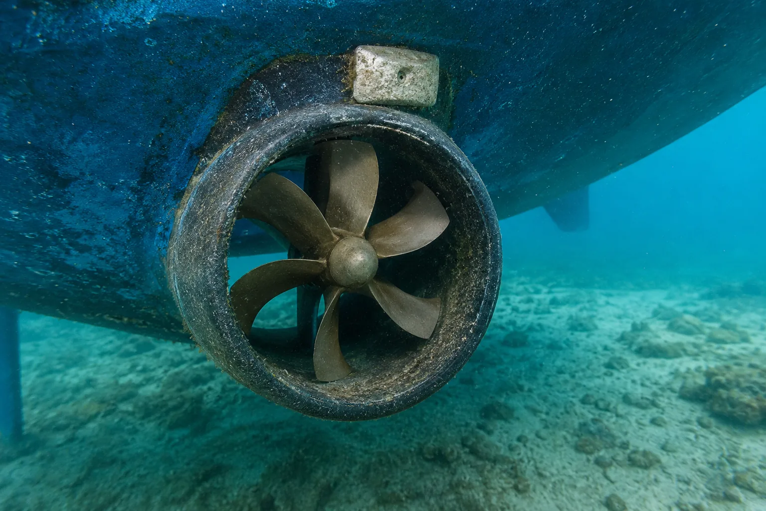
Bow Thruster Maintenance, Common Problems, Diagnosis and Repair
A complete practical guide to maintaining, inspecting and troubleshooting electric tunnel and retractable bow thrusters. It covers preventive maintenance, batteries and high-current wiring, propellers, anodes, motor brushes, contactors, gear legs, common symptoms, confirmation tests, repair procedures and a final step-by-step problem-solving workflow.
How a bow thruster works
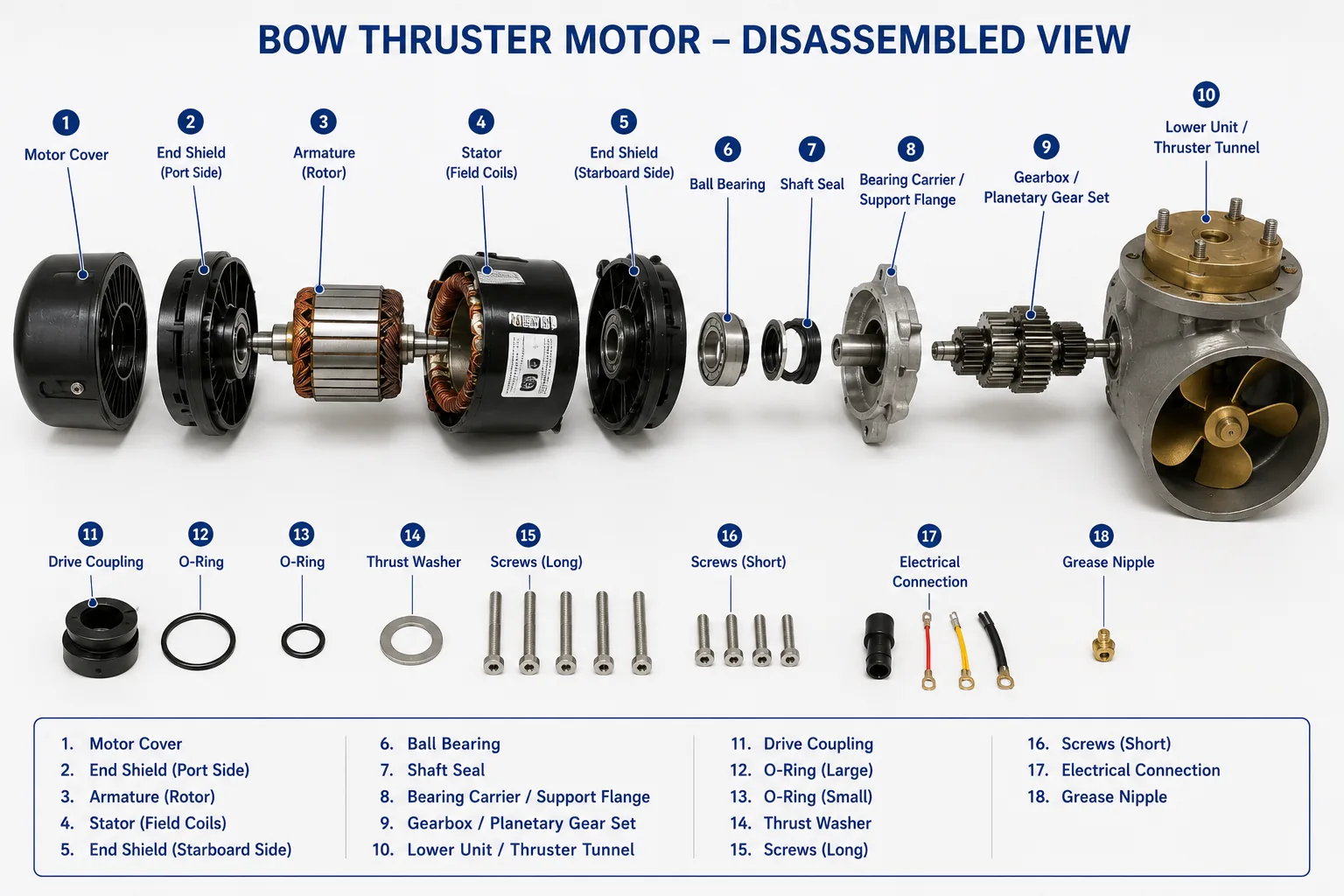
A typical electric bow thruster consists of a dedicated or shared battery bank, battery isolator, high-current fuse or breaker, heavy positive and negative cables, contactors or an electronic motor controller, an electric motor, a coupling, a gear leg, propeller, tunnel, control panel and sacrificial anode. Moving the joystick sends a low-current command to the controller, which applies high current to the motor in the required direction. The motor drives the propeller and accelerates water sideways through the tunnel.
Because the system combines seawater exposure, large current, short high-load operating cycles and mechanical transmission, most faults originate from one of five areas: insufficient voltage, poor electrical connections, fouling or obstruction, worn switching/motor components, or corrosion and seal failure.
Interactive bow thruster symptom finder
Enter observations such as clicks but does not run, weak thrust, works one direction, fuse blows, overheats or grinding noise. The tool searches the fault sections and ranks likely matches.
Fast triage: what should you check first?
| Symptom | First safe check | Stop and isolate immediately when |
|---|---|---|
| Nothing happens | Panel power, battery voltage, isolator, main fuse and control fuse. | Connections are hot, burned, wet or incorrectly protected. |
| Only a click | Measure voltage directly at the motor during the command. | Cables smoke, voltage collapses or current is abnormally high. |
| Weak thrust | Check motor voltage under load, battery condition and tunnel/propeller fouling. | Motor overheats, grinding begins or propeller damage is visible. |
| Motor runs, no thrust | Inspect propeller, drive pin, coupling and gear leg. | Rattling, metal fragments or seal leakage is present. |
| Fuse repeatedly opens | Inspect for mechanical blockage and verify correct fuse type/rating. | A second correct fuse opens or cable insulation is damaged. |
| Stops after short use | Allow cooling, review duty cycle, then measure voltage/current. | Shutdown repeats after light use or motor/cables become very hot. |
| Water or corrosion | Isolate power and identify whether leakage is internal or underwater. | Water reaches motor/controller or gear oil is contaminated. |
Preventive bow thruster maintenance
1. Inspect before every departure or manoeuvring-intensive trip
- Confirm the control panel arms normally and no warning is displayed.
- Test a very short pulse in both directions while the boat is safely secured and the tunnel is submerged.
- Listen for a changed sound, delayed response, grinding, excessive vibration or contactor chatter.
- Check the thruster battery state of charge and confirm the main isolator is in the intended position.
- For retractable units, confirm full deployment and retraction before leaving the berth.
2. Maintain the battery and high-current circuit
- Keep the battery fully charged and test its capacity, not only its open-circuit voltage.
- Measure voltage directly at the thruster while operating. The usable limit is model-specific; excessive drop reduces thrust and increases heat.
- Inspect battery posts, isolator, fuse holder, contactors, motor terminals and ground points for looseness, corrosion and heat discoloration.
- Clean connections to bright metal, replace damaged lugs and tighten to the specified torque.
- Check that cable size, length, fuse class and battery type match the installation documentation.
- With lithium batteries, verify that the battery-management system can supply the thruster’s peak current without disconnecting.
3. Clean the tunnel, propeller and gear leg
- At haul-out, remove barnacles, algae, rope, fishing line and hard deposits from the tunnel, propeller and gear leg.
- Use plastic or non-damaging tools around the propeller and coatings.
- Inspect the tunnel surface and edges for impact damage, delamination, cracks or repairs that disturb water flow.
- Apply only approved antifouling. Do not coat the sacrificial anode, propeller-shaft contact areas, seals or clearances prohibited by the manufacturer.
- During the season, investigate any sudden loss of thrust because a wrapped line can damage seals quickly.
4. Inspect the propeller and drive components
- Check every blade for cracks, deformation, erosion and impact damage.
- Confirm the propeller is secure and installed in the correct orientation.
- Inspect the drive pin or shear pin, nut, locking tab, washer and shaft splines.
- Rotate only as permitted by the manual and feel for abnormal play, scraping or rough bearings.
- Replace damaged parts; do not attempt to reshape a badly distorted composite propeller.
5. Inspect and replace the sacrificial anode
- Inspect at least annually and more often in marinas with known corrosion activity.
- Replace when approximately half consumed, when loose, cracked or electrically isolated, or at the manufacturer interval.
- Fit the exact material and part number specified for the thruster and operating water.
- Clean the contact surface so the anode has direct electrical contact with the protected metal.
- Never paint or heavily coat the anode.
6. Service motor brushes, contactors and ventilation
- Brushed motors create carbon dust and their brush length decreases with operating time.
- Inspect brushes at the model-specific interval and replace the full approved set before the service limit.
- Inspect the commutator for burning, grooving and contamination.
- Check contactors for pitted contacts, sticking, chatter and overheating.
- Keep the motor compartment dry and ventilated without compromising required protection.
- Brushless and proportional systems require controller diagnostics rather than brush replacement.
7. Inspect seals, gear leg and water ingress
- Look for oil leakage, milky lubricant, salt trails, rust or water around the motor/gear leg interface.
- Replace serviceable gear oil only at the specified interval and with the specified lubricant.
- Do not ignore fishing line around the shaft; it can cut a seal.
- Pressure or vacuum testing should follow the manufacturer’s service procedure.
- Repair deck, hatch or condensation leaks that drip onto the motor and electrical terminals.
8. Operate the thruster correctly
- Use short pulses rather than one long continuous run.
- Pause between operations and respect the published duty cycle.
- Avoid instant full-power reversal; allow the propeller to slow unless the manufacturer’s proportional controller handles reversal.
- Use the thruster mainly at very low vessel speed. Water flow across the tunnel can greatly reduce side thrust.
- Do not use the thruster as a substitute for sound boat handling in extreme wind or current.
Recommended maintenance schedule
| Interval | Maintenance task | Evidence to record |
|---|---|---|
| Before departure / regularly in season | Panel check, short test both directions, unusual noise, battery state, retractable deployment. | Fault code, sound change, response time. |
| Monthly in active season | Inspect accessible cables, terminals, fuse holder, motor compartment moisture and battery charging. | Voltage at rest, visible heat/corrosion. |
| At haul-out / at least annually | Clean tunnel and propeller; inspect propeller, drive pin, anode, gear leg, seals and antifouling. | Photos of anode, propeller and tunnel. |
| Annually | Load-test battery, measure motor voltage/current, torque-check approved connections and test thermal protection. | Voltage drop, current draw and battery test result. |
| Manufacturer service interval | Brush inspection, contactor service, gear lubricant, seals, controller diagnostics and retractable mechanism service. | Brush length, fault history, lubricant condition. |
| Immediately after impact, rope entanglement or fuse event | Stop use and inspect propeller, shaft, seals, gear leg and current draw. | Damage photos and measured current. |
1. Bow Thruster Is Completely Inoperative
Symptoms
- The control panel does not illuminate or arm.
- No relay click, motor sound or propeller movement is heard in either direction.
- The thruster may have worked previously and then stopped without warning.
- Other 12 V or 24 V equipment may still operate normally.
Most likely causes
- Thruster battery is discharged, disconnected or internally damaged.
- Main battery isolator, circuit breaker or high-current fuse is open.
- Control-panel fuse, emergency stop or enable circuit is open.
- Loose, corroded or overheated battery, ground or control-cable connection.
- Control panel, wiring harness or electronic control module has failed.
- Thermal protection is still active after heavy use.
How to confirm the fault
- Secure the boat and make sure nobody is near the tunnel. Switch the thruster off before touching wiring.
- Check whether the control panel powers up and whether any fault code, alarm tone or flashing LED is present.
- Measure battery voltage directly at the battery posts, not on the cable clamps.
- Check the main isolator, high-current fuse and breaker with a multimeter. A fuse can appear intact while being electrically open.
- Measure voltage at the thruster motor or controller input. If battery voltage exists at the battery but not at the thruster, trace the positive and negative supply path.
- Check the low-current control fuse, panel connector and harness continuity.
- Allow the unit to cool for the manufacturer-specified period and retest once. If it repeatedly trips, continue diagnosis rather than repeatedly resetting it.
Repair procedure
- Charge and load-test the thruster battery; replace it if capacity or internal resistance is unacceptable.
- Clean and tighten cable lugs and ground points. Replace heat-damaged, green, brittle or undersized cables.
- Replace a failed fuse or breaker only with the exact approved type and rating, after finding the reason it opened.
- Repair a failed isolator, emergency-stop circuit, panel connector or damaged harness.
- Replace or professionally test the control panel or electronic controller when correct power and ground are present but the system remains inactive.
- After repair, test both directions in short pulses and inspect every high-current connection for abnormal heating.
Basic tools
- Digital multimeter
- Insulated socket and spanner set
- Fuse puller
- Battery terminal brush
- Flashlight
- Electrical contact cleaner approved for marine use
Professional diagnostic equipment
- Battery conductance/load tester
- DC clamp ammeter
- Milliohm meter
- Thermal camera
- Manufacturer diagnostic interface
2. Relay Clicks but the Motor Does Not Run
Symptoms
- A strong click is heard when the joystick is moved, but there is no motor rotation.
- The panel remains powered and may show no fault.
- The motor may work intermittently after several attempts.
- Battery voltage or cabin lights may dip sharply during the command.
Most likely causes
- Weak battery or severe voltage drop in the high-current circuit.
- Burned, pitted or welded contactor/solenoid contacts.
- Worn or sticking carbon brushes in a brushed DC motor.
- Motor armature or bearings are seized.
- Propeller or gear leg is mechanically jammed.
- Loose internal motor connection or failed winding.
How to confirm the fault
- Do not continue commanding the thruster if cables become hot, smoke appears or the fuse opens.
- Measure voltage directly at the motor terminals while the command is applied. Compare it with the battery voltage measured at the same moment.
- Perform positive-side and negative-side voltage-drop tests under load.
- Use a DC clamp meter to observe current. Very high current with no rotation suggests a mechanical lock or motor fault; very low current after a click suggests poor contactor conduction or an open motor circuit.
- With power isolated and the boat safely hauled or a diver using proper procedures, inspect the propeller and tunnel for rope, debris or marine growth.
- Inspect motor brushes and commutator only according to the model service manual.
- Bench-test the motor and contactor assembly if onboard measurements do not isolate the fault.
Repair procedure
- Charge or replace the battery and correct cable sizing or connection resistance.
- Replace a burned contactor or solenoid assembly rather than filing heavily damaged high-current contacts.
- Clean the brush area and replace brushes as a complete approved set when below the service limit.
- Remove rope or debris and replace a damaged propeller, drive pin or gear components.
- Repair or replace a seized or electrically failed motor.
- Verify normal current draw, voltage at the motor and equal operation in both directions after repair.
Basic tools
- Digital multimeter
- DC clamp meter
- Socket set
- Insulated tools
- Inspection light
Professional diagnostic equipment
- High-current load tester
- Thermal camera
- Motor insulation tester where approved
- Contactor bench test setup
- Manufacturer current specifications
3. Thruster Runs in Only One Direction
Symptoms
- The thruster works normally to port but not to starboard, or vice versa.
- One direction produces a click while the other produces no response.
- The fault may change when the joystick or panel is moved.
- The motor may run in both directions during a direct professional bench test.
Most likely causes
- One directional contactor or relay has failed.
- Joystick or control-panel directional switch has failed.
- Open or corroded control wire, connector pin or harness branch.
- Electronic controller has a directional output fault.
- One propeller direction is mechanically obstructed or a dual-propeller component is damaged.
How to confirm the fault
- Record exactly which direction works and whether a click is heard in the failed direction.
- Check for fault codes and verify panel supply voltage.
- Measure the directional command signal at the contactor/controller input while operating the joystick.
- Swap only manufacturer-approved diagnostic connectors or use the official test procedure; do not bridge high-current terminals.
- If the command arrives but the contactor output does not switch, test or replace that contactor.
- If the command does not arrive, test the joystick, panel and harness continuity.
- Inspect the propeller system for damage if electrical reversal works but thrust is absent in one direction.
Repair procedure
- Replace the failed directional contactor or complete matched contactor assembly.
- Repair damaged connectors, pins or control wiring and seal them against moisture.
- Replace or reconfigure the control panel/controller if it does not issue the correct command.
- Repair damaged dual-propeller components or replace the propeller and drive pin as required.
- Test repeated short commands in both directions and confirm that direction matches the panel indication.
Basic tools
- Multimeter
- Continuity leads
- Small insulated screwdrivers
- Connector tools
- Wiring diagram
Professional diagnostic equipment
- Manufacturer diagnostic cable/software
- Oscilloscope or logic probe where appropriate
- Contactor test fixture
4. Bow Thruster Produces Weak Thrust
Symptoms
- The motor runs, but the bow moves much less than before.
- Motor speed sounds low or changes noticeably under load.
- Performance is worse after long periods in the water.
- Thrust is acceptable at first and then quickly falls.
Most likely causes
- Low battery voltage or battery capacity loss.
- Excessive voltage drop through undersized, long, loose or corroded cables.
- Marine growth on the tunnel, gear leg or propeller.
- Damaged, incorrectly installed or partially missing propeller.
- Cavitation or air being drawn into the tunnel.
- Motor brushes, commutator, bearings or controller are worn.
- Boat speed, wind or current exceeds the thruster's practical capability.
How to confirm the fault
- Measure voltage directly at the thruster during operation and compare it with the manufacturer’s minimum operating voltage.
- Measure current draw and compare with the model data. Low speed with high current suggests overload; low current may indicate poor contact or controller limitation.
- Inspect the tunnel, propeller and gear leg for growth, damage and correct installation.
- Check whether the tunnel opening is near the water surface or draws air at certain loading conditions.
- Confirm that the battery is fully charged and passes a load or conductance test.
- Inspect all high-current connections for heat discoloration and measure voltage drop under load.
- Compare performance in calm water with the boat nearly stationary; a tunnel thruster loses effectiveness as forward speed increases.
Repair procedure
- Charge or replace the battery and install the correct cable cross-section and connection hardware.
- Clean the tunnel, propeller and gear leg; apply only manufacturer-approved antifouling while keeping anodes and specified clearances uncoated.
- Replace damaged or worn propellers and secure them with the correct drive pin, nut and locking method.
- Correct installation or operational causes of air ingestion where practical.
- Service brushes, commutator, bearings or controller after confirming the electrical supply is healthy.
- Use short, controlled pulses and do not expect the thruster to overcome excessive vessel speed, windage or current.
Basic tools
- Multimeter
- DC clamp meter
- Battery tester
- Plastic scraper
- Propeller removal tools
- Inspection mirror
Professional diagnostic equipment
- Thermal camera
- Milliohm meter
- Underwater inspection camera
- Motor current logger
5. Motor Runs but There Is No Thrust
Symptoms
- The electric motor can be heard spinning at normal or unusually high speed.
- No meaningful water flow or bow movement is produced.
- A sudden loss of thrust may have occurred after impact or rope entanglement.
- Grinding or rattling may be heard from the tunnel or gear leg.
Most likely causes
- Propeller is missing, loose, broken or stripped.
- Drive pin, shear pin or coupling has failed.
- Gear leg or internal gearbox is damaged.
- Motor-to-gear-leg coupling is disconnected or stripped.
- Propeller rotates on the shaft without transmitting torque.
- On retractable units, the leg has not fully deployed.
How to confirm the fault
- Stop using the thruster immediately to avoid further gear damage.
- Isolate power and inspect the propeller after haul-out or by a qualified diver.
- Check propeller attachment, drive pin and shaft condition.
- Manually inspect permitted components for free play according to the service manual.
- Listen for gear engagement and inspect gear oil only on models designed with a serviceable oil reservoir.
- On retractable systems, confirm full deployment, position sensors and locking mechanism.
- Remove and bench-inspect the motor/gear assembly when external parts are intact.
Repair procedure
- Replace the propeller, drive pin, nut and locking components with model-specific parts.
- Repair or replace a stripped coupling or damaged shaft.
- Overhaul or replace the gear leg when gears, bearings or seals are damaged.
- Repair deployment mechanism or position sensing on retractable models.
- After assembly, rotate and clearance-check the propeller as specified before energizing.
- Test in both directions for noise, vibration, leaks and full water flow.
Basic tools
- Propeller puller where required
- Socket/hex-key set
- Torque wrench
- Inspection light
- Replacement locking hardware
Professional diagnostic equipment
- Gear-leg service tools
- Dial indicator
- Borescope
- Pressure/vacuum leak test equipment
6. Main Fuse or Breaker Repeatedly Opens
Symptoms
- The main fuse opens as soon as the thruster is commanded.
- The breaker trips after one or several short operations.
- A replacement fuse fails again.
- High-current cables, contactor or motor may smell hot.
Most likely causes
- Propeller is jammed by rope, debris or hard marine growth.
- Motor, controller or cable has a short circuit or insulation failure.
- Contactor is welded or internally damaged.
- Incorrect fuse type or rating has been installed.
- Motor current is excessive because of worn bearings, gear damage or low voltage.
- Battery or wiring has been incorrectly modified.
How to confirm the fault
- Do not install progressively larger fuses. Isolate the system.
- Inspect the tunnel and propeller for blockage before electrical testing.
- Compare the installed fuse class and rating with the exact manufacturer specification.
- Inspect cables for crushed insulation, chafing, water ingress and incorrect polarity.
- Measure motor and cable insulation only using methods approved for the electronics fitted.
- Use a current-limited professional test or clamp-current measurement with the correct fuse installed.
- Bench-test the motor, contactor and controller separately when a short or excessive current remains suspected.
Repair procedure
- Remove the mechanical blockage and replace damaged propeller or gear components.
- Replace shorted or heat-damaged cables, contactors, controller or motor.
- Correct cable routing, support and overcurrent protection.
- Install only the specified marine-rated fuse/breaker and holder.
- Repair bearing or gearbox drag that causes excessive current.
- Run a controlled test while measuring voltage and current, then recheck connection temperature.
Basic tools
- Multimeter
- Correct spare fuse
- Insulated tools
- Flashlight
- Cable inspection mirror
Professional diagnostic equipment
- DC clamp meter with inrush capture
- Insulation tester only where permitted
- Thermal camera
- Current-limited power source
- Motor test bench
7. Thruster Overheats or Shuts Down After a Few Seconds
Symptoms
- The thruster stops during repeated manoeuvring and works again after cooling.
- A thermal alarm, code or flashing indicator appears.
- The motor housing or cables become unusually hot.
- Available run time becomes shorter than it used to be.
Most likely causes
- Normal thermal protection caused by exceeding the duty cycle.
- Low voltage makes the motor draw excessive current and heat.
- Propeller or gear leg is fouled or partially jammed.
- Motor brushes, bearings or commutator are worn.
- Ventilation around the motor is poor or the compartment is excessively hot.
- Incorrect controller settings or a failing temperature sensor.
How to confirm the fault
- Stop operation and let the unit cool naturally; do not bypass thermal protection.
- Review the exact model’s duty-cycle limits and recent operating pattern.
- Measure voltage and current during operation.
- Inspect tunnel and propeller loading.
- Check motor ventilation, dust buildup and signs of water or corrosion.
- Test temperature sensor resistance or diagnostic value using manufacturer data.
- Compare motor current and temperature rise with a known-good baseline.
Repair procedure
- Operate in shorter pulses with pauses and avoid rapid full-power reversing.
- Restore correct supply voltage and cable condition.
- Clean the propeller/tunnel and repair mechanical drag.
- Replace worn brushes, bearings, motor or sensor as confirmed.
- Improve compartment ventilation only in a way that preserves required water and ignition protection.
- Reset or configure electronic controls only according to the manufacturer procedure.
Basic tools
- Multimeter
- DC clamp meter
- Non-contact thermometer
- Cleaning tools
- Service manual
Professional diagnostic equipment
- Thermal camera
- Data logger
- Manufacturer diagnostics
- Motor current/temperature test setup
8. Excessive Vibration, Grinding or Unusual Noise
Symptoms
- The tunnel vibrates more than normal.
- Grinding, knocking, scraping or rattling is heard.
- Noise is different in port and starboard directions.
- Thrust may be reduced and the motor current may rise.
Most likely causes
- Damaged, cracked, distorted or incorrectly fitted propeller.
- Rope, fishing line, plastic or debris is wrapped around the shaft.
- Loose propeller nut, motor mount, gear leg or tunnel hardware.
- Worn gear-leg bearings or damaged gears.
- Motor bearings or coupling are worn.
- Cavitation caused by air ingestion or poor tunnel flow.
How to confirm the fault
- Stop immediately if grinding, sudden severe vibration or water leakage is present.
- Inspect the tunnel and propeller with the system isolated.
- Check propeller clearance, attachment and evidence of contact with the tunnel.
- Check accessible fasteners and motor mount according to torque specifications.
- Compare noise and current in both directions.
- Inspect gear leg and motor bearings for play after disassembly where permitted.
- Determine whether the sound is mechanical or cavitation-related by observing water flow and air ingestion.
Repair procedure
- Remove entangled material and inspect seals before returning the unit to service.
- Replace a damaged propeller and all required fastening/locking parts.
- Tighten or repair loose mounts and hardware to specified torque.
- Overhaul or replace worn motor bearings, coupling or gear leg.
- Correct installation conditions that cause air ingestion where practical.
- Perform a low-power then full-power test in both directions and recheck for leaks.
Basic tools
- Inspection light
- Propeller tools
- Torque wrench
- Plastic scraper
- Mirror
Professional diagnostic equipment
- Dial indicator
- Vibration meter
- Borescope
- Underwater camera
- Bearing and gear service tools
9. Water Ingress, Corrosion or Gear-Leg Seal Failure
Symptoms
- Rust, green corrosion, salt deposits or moisture are visible around the motor or terminals.
- Gear oil is milky, water-contaminated or leaking on serviceable models.
- An anode disappears rapidly or metal parts show pitting.
- The system becomes intermittent, trips fuses or produces bearing noise.
Most likely causes
- Failed shaft seal, O-ring, gasket or gear-leg seal.
- Condensation or hatch/deck leakage onto the motor and electrical parts.
- Poor cable sealing or damaged gland.
- Missing, painted, incorrect or exhausted sacrificial anode.
- Galvanic or stray-current corrosion.
- Incorrect antifouling coating applied to anode or incompatible metal.
How to confirm the fault
- Isolate power immediately if water has reached the motor, controller or high-current terminals.
- Identify whether moisture entered from inside the vessel or through the underwater gear leg.
- Inspect anode condition and electrical bonding only according to the manufacturer’s installation design.
- Inspect gear oil, seals and drain plugs on serviceable models.
- Check for stray DC current and incorrect shore-power bonding with qualified equipment.
- Inspect cable glands, deck hatches and compartment drainage.
- Pressure/vacuum test a removed gear leg where the service manual specifies it.
Repair procedure
- Dry, clean and replace water-damaged electrical components; do not merely spray over corrosion.
- Replace failed seals, O-rings and gaskets and inspect shaft/bearing surfaces for wear.
- Repair the source of deck, hatch or condensation water.
- Fit the exact approved anode and keep it free of paint and heavy contamination.
- Correct stray-current or bonding faults through a qualified marine electrician.
- Refill serviceable gear oil with the specified lubricant and verify leak-free operation.
Basic tools
- Inspection light
- Multimeter
- Absorbent materials
- Seal picks
- Correct lubricant and drain container
Professional diagnostic equipment
- Pressure/vacuum tester
- Insulation-resistance equipment where approved
- Silver/silver-chloride reference electrode
- Stray-current diagnostic equipment
10. Sacrificial Anode Wears Out Too Quickly
Symptoms
- The thruster anode is more than half consumed long before annual haul-out.
- Gear-leg metal shows pitting despite a recently installed anode.
- Anodes elsewhere on the vessel also disappear rapidly.
- Consumption changes after shore-power, charger or electrical modifications.
Most likely causes
- Incorrect anode material for the water type or manufacturer requirement.
- Stray DC current or galvanic current from shore-power connection.
- Anode has poor electrical contact with the protected metal.
- Additional incompatible underwater metals or bonding modifications.
- Paint, sealant or corrosion prevents correct anode contact.
- Normal high-consumption environment requiring more frequent inspection.
How to confirm the fault
- Verify the part number and anode material specified for the thruster and operating water.
- Remove the anode and inspect the mating surface for clean metal-to-metal contact.
- Inspect other vessel anodes and note whether the issue is local or vessel-wide.
- Review recent shore-power, inverter, charger, battery or bonding work.
- Have a qualified technician measure hull potential and test for stray current.
- Check that the anode has not been painted or coated.
Repair procedure
- Install the correct approved anode on a clean contact surface.
- Do not apply antifouling or protective coating to the anode.
- Repair shore-power isolation, bonding or DC leakage faults as diagnosed.
- Replace damaged gear-leg parts if corrosion has compromised strength or sealing.
- Increase inspection frequency until the consumption rate is understood.
- Record anode condition with dated photographs at each service.
Basic tools
- Correct replacement anode
- Socket/hex-key set
- Wire brush or abrasive pad
- Camera
Professional diagnostic equipment
- Hull-potential reference electrode
- Galvanic isolator test equipment
- Stray-current meter
11. Control Panel Alarms, Communication Faults or Intermittent Operation
Symptoms
- The panel flashes, beeps or displays an error code.
- The system arms and disarms unexpectedly.
- Commands are delayed or intermittent.
- Multiple control stations behave differently.
Most likely causes
- Low control voltage or unstable supply.
- Loose, wet or corroded panel/harness connector.
- Damaged communication cable or incorrect termination on networked systems.
- Panel calibration, configuration or pairing is incorrect.
- Temperature, current or position sensor fault.
- Defective panel, gateway or electronic controller.
How to confirm the fault
- Record the exact code, LED sequence and conditions when it appears.
- Consult the model-specific manual; code meanings are not universal.
- Measure control-supply voltage during operation.
- Inspect and reseat connectors with power isolated.
- Test each control station separately and inspect network termination where applicable.
- Use manufacturer diagnostics to view sensor values and stored faults.
- Substitute a known-good panel or harness only when the manufacturer procedure permits it.
Repair procedure
- Restore stable supply voltage and grounds.
- Clean, repair or replace corroded connectors and damaged harness sections.
- Correct network termination, panel pairing or configuration.
- Replace the confirmed failed sensor, panel, gateway or controller.
- Seal and support wiring to prevent vibration and moisture recurrence.
- Clear stored faults and perform a complete functional test from every control station.
Basic tools
- Multimeter
- Connector tools
- Contact cleaner approved by manufacturer
- Wiring diagram
Professional diagnostic equipment
- Manufacturer diagnostic interface
- Network analyzer where applicable
- Known-good test panel/harness
12. Retractable Bow Thruster Does Not Deploy or Retract
Symptoms
- The unit does not lower into the water or does not return into the hull.
- The hatch or leg stops partway.
- The motor is inhibited because deployment is not confirmed.
- Alarm codes indicate position, actuator or hatch faults.
Most likely causes
- Low voltage or failed actuator supply.
- Mechanical obstruction, marine growth or damaged hatch.
- Failed actuator, hydraulic component, limit switch or position sensor.
- Misalignment or worn deployment mechanism.
- Water ingress into actuator/control components.
- Emergency/manual retraction procedure has been incorrectly reset.
How to confirm the fault
- Do not operate the vessel at speed with a partially deployed unit.
- Check the exact emergency securing procedure in the manufacturer manual.
- Inspect for visible obstruction without entering an unsafe area.
- Measure actuator supply voltage and control signals.
- Read deployment position and sensor states using the diagnostic system.
- Inspect mechanical linkages, hatch alignment and signs of water ingress.
- Test actuator/hydraulic pressure and limit switches according to the service procedure.
Repair procedure
- Remove the obstruction and clean growth from the deployment cavity.
- Repair or replace the hatch, linkage, actuator, hydraulic component or sensor.
- Correct alignment and set limits/calibration.
- Repair water ingress and damaged connectors.
- Manually secure the unit in the safe retracted position if repair cannot be completed.
- Perform repeated dockside deploy/retract cycles before returning to service.
Basic tools
- Multimeter
- Inspection light
- Basic hand tools
- Manufacturer emergency procedure
Professional diagnostic equipment
- Manufacturer diagnostics
- Hydraulic pressure gauge where applicable
- Alignment fixtures
- Actuator test equipment
Step-by-step bow thruster problem solving
Use this sequence from the safest and simplest checks toward invasive testing. Do not skip directly to replacing the motor or controller.
Make the boat and system safe
Secure the vessel, stop the engine if required, keep people away from the tunnel, switch off the thruster panel and isolate the thruster battery before physical inspection. For an in-water underwater inspection, use a qualified diver and procedures that prevent accidental activation.
Define the exact symptom
Record whether the panel powers up, whether a click is heard, which direction fails, whether the motor rotates, how long it runs, whether the fuse opens, and whether thrust, noise or vibration changed suddenly. Record any code or LED sequence before cycling power.
Perform a visual and smell inspection
Look for water, rust, green corrosion, burned insulation, loose lugs, melted fuse holders, carbon dust, oil leakage and damaged connectors. A burnt smell or hot terminal often identifies high resistance before electrical measurements begin.
Check the mechanical load
With power isolated, inspect the tunnel and propeller for rope, fishing line, marine growth, a broken blade, loose propeller or missing drive pin. A blocked propeller can cause low thrust, thermal shutdown, fuse failure and motor damage.
Verify battery condition
Measure open-circuit voltage at the battery posts, then perform a load or conductance test. A battery can show acceptable resting voltage but collapse under the hundreds of amperes demanded by a thruster.
Measure voltage at the thruster under load
Reconnect only when safe and measure directly at the motor/controller input during a short command. Compare this with simultaneous battery-post voltage. Low voltage at both points suggests battery weakness; a large difference suggests cable, isolator, fuse-holder, contactor or connection resistance.
Perform voltage-drop tests
Measure from battery positive post to thruster positive terminal while operating, then from battery negative post to motor/controller negative. Test individual sections to find the resistive connection. Use model-specific limits because acceptable drop depends on system voltage and installation.
Measure current and interpret it
Compare measured current with the model data. Very high current with low or zero speed points toward mechanical blockage, bearing/gear drag or motor fault. Low current with a relay click can indicate burned contactor contacts, an open motor circuit or controller limitation. Low voltage can itself increase heating and reduce performance.
Separate the control circuit from the power circuit
If the panel does not command one direction, test joystick output, harness continuity and controller input. If the correct command reaches the contactor/controller but power is not delivered to the motor, diagnose the contactor or controller. Never bypass safety interlocks or bridge high-current terminals as a casual test.
Inspect motor, brushes and contactors
After confirming a healthy battery, cables and mechanical load, inspect brushed-motor brushes and commutator, contactor condition, bearings and internal connections according to the service manual. Brushless and proportional units should be diagnosed through their controller and sensor data.
Inspect gear leg, coupling and seals
If the motor runs without thrust, or grinding, leakage or propeller free play is present, inspect the drive pin, coupling, shaft, gears, bearings and seals. Repair seal failures before water causes secondary damage.
Repair only the confirmed cause
Do not replace the battery, motor, controller or gear leg based only on a symptom. Use measurements and inspection to confirm the failed stage, then fit exact approved parts and follow torque, lubrication, sealing and wiring instructions.
Complete a controlled post-repair test
Test short pulses in both directions while measuring voltage and current. Confirm full thrust, correct direction, normal sound, no abnormal heating, no leakage and no fault codes. For retractable units, cycle deployment and retraction repeatedly at the dock.
Document the result
Record battery test values, motor voltage, voltage drop, current draw, replaced parts, torque-critical work, anode condition and photographs. A baseline makes the next diagnosis much faster and supports planned maintenance.
When to call a professional
- The main fuse repeatedly opens with the correct rating.
- High-current cables, contactors or terminals overheat.
- Water has entered the motor, controller or gear leg.
- Gear oil is milky, metal particles are present or grinding continues.
- The motor requires bench testing, rewinding or bearing replacement.
- Stray-current or galvanic corrosion is suspected.
- A retractable unit cannot be safely secured in the retracted position.
- The installation uses a networked proportional controller, lithium battery bank or hydraulic system requiring specialist diagnostics.
Manage bow thruster inspections and repairs digitally
TwoBoat Fleet Maintenance and Work Order Management can be used to schedule annual thruster service, record battery and current measurements, attach haul-out photographs, track anode replacement, assign technicians, store parts and maintain a complete repair history for every vessel.
Explore Fleet Maintenance Software · Explore Work Order Management · Explore Charter Management Software
Frequently asked questions
How often should a bow thruster be serviced?
Perform functional and visual checks during the season and a thorough underwater inspection at least annually or at every haul-out. Battery, cable, brush, lubricant and retractable-mechanism intervals depend on the exact model and operating hours.
Why is my bow thruster weak even though the motor runs?
The most common areas to check are voltage at the motor under load, battery capacity, high-current cable voltage drop, marine growth, propeller damage and cavitation or air ingestion.
Can I use a larger fuse if the bow thruster keeps blowing the existing one?
No. Use only the specified fuse class and rating. Repeated fuse failure indicates excessive current, a short circuit, mechanical blockage, motor/gear fault or incorrect wiring that must be diagnosed.
Should antifouling be applied inside the bow thruster tunnel?
Approved antifouling may be used on permitted tunnel, propeller or gear-leg surfaces, but never paint the sacrificial anode or prohibited shaft, seal and clearance areas. Follow the exact manufacturer guidance.
Why does the thruster stop and work again later?
Thermal protection may have activated because the duty cycle was exceeded, voltage was low, the propeller was fouled or motor/mechanical wear increased current and heat.
When should the anode be replaced?
Replace it at the manufacturer interval, when roughly half consumed, when damaged or when reliable metal-to-metal contact is lost. Rapid consumption requires investigation for galvanic or stray-current problems.
Can a bow thruster be tested while the boat is out of the water?
Only according to the manufacturer’s procedure and usually only for a very brief functional check. Running unloaded or operating a retractable mechanism incorrectly can damage components. Never stand near the propeller.
Continue reading
Build your Croatia sailing knowledge with related TwoBoat guides, software, guides and planning tools.