
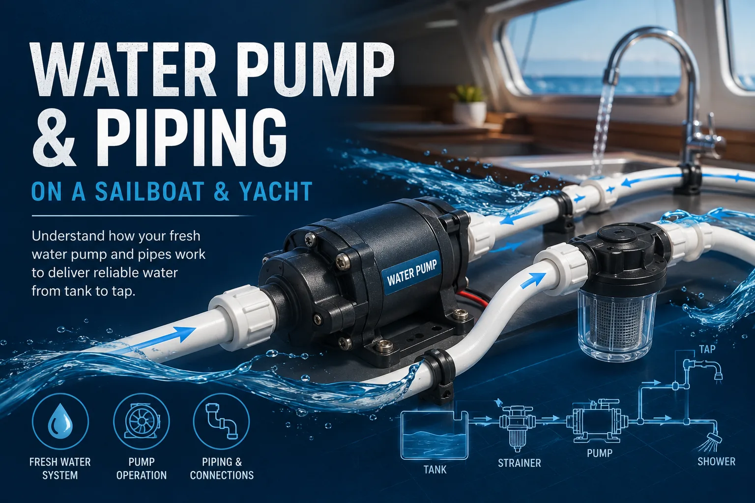
Fresh Water System on a Sailboat & Yacht
Understand the complete pressurized fresh-water system—from tank to tap. Learn how pressure pumps switch automatically, what an accumulator does, and how to diagnose no flow, low pressure, pulsing, continuous pump operation, leaks and air entering the suction side.
How the system works
Water normally flows from one or more tanks through a selector valve and suction strainer to a 12 V or 24 V pressure pump. Opening a tap lowers pressure. A conventional pump's pressure switch starts the motor; closing the tap lets pressure rise until the pump reaches cut-out pressure and stops.
Diaphragm pump
The common domestic pressure pump. Multi-chamber diaphragms provide flow and many units include a pressure switch.
Variable-speed pump
Electronic control changes pump speed with demand for steadier pressure and fewer cycles.
Accumulator
An air cushion stores a small volume under pressure and reduces short cycling.
Calorifier
The hot-water vessel may use engine coolant, shore-power heating or other installed heat sources.
What the Fresh-Water System Does on a Boat
The domestic fresh-water system stores potable water and delivers it on demand to the galley, heads, showers, deck shower and other installed consumers. Unlike a gravity-fed bottle or tank, most modern sailboats and yachts use a pressure pump so the taps behave much like those in a house: open a tap and water flows; close it and the pump eventually stops automatically.
One or more tanks carry the vessel's usable fresh-water supply independently of seawater.
The pressure pump converts stored water into useful flow and pressure for taps, showers and appliances.
Cold-water pipework feeds consumers directly and also supplies the water heater.
The calorifier/water heater creates a hot-water branch that runs alongside the cold-water branch.
A strainer keeps larger debris out of the pump, while correct fusing, valves and relief devices protect the system.
Selectors, isolation valves and manifolds allow tanks or branches to be selected, serviced or shut down.
Complete Water Path — From Deck Fill to Tap
This is the complete functional path found on many cruising sailboats and yachts. Move the pointer over a component, focus it with the keyboard, or click it to see what it does and what usually goes wrong.
Hover over or click a component to see its function, installation notes and typical failure symptoms.
How the System Operates Step by Step
Water is stored
Potable water enters through the deck fill and is stored in one or more tanks. The tank vent allows displaced air to escape during filling and lets air return as water is consumed.
The pump receives water
A selector valve may choose between multiple tanks. Water then passes through the suction hose and strainer before reaching the pressure pump. The suction side must be airtight: a fitting can leak air without visibly leaking water.
Opening a tap creates demand
When a tap or shower opens, system pressure falls. On a conventional pressure-switch pump, the switch detects this pressure drop and starts the 12 V or 24 V motor.
The diaphragm moves water
The motor drives an eccentric mechanism that repeatedly flexes one or more diaphragms. Inlet and outlet check valves make the flow move in one direction—from the tank toward the pressurized plumbing.
The accumulator buffers pressure
If fitted, an accumulator stores a small quantity of pressurized water against an air cushion. This can reduce rapid pump cycling and make small demands smoother.
Cold and hot branches separate
The cold manifold feeds cold taps directly and normally also feeds the inlet of the water heater. Heated water leaves the calorifier through a separate hot-water pipe and reaches mixer taps or showers.
Closing the tap stops the pump
When demand stops, the pump continues briefly until pressure reaches its cut-out threshold. The pressure switch then stops the motor. A healthy closed system should hold pressure rather than repeatedly restarting the pump.
Typical Fresh-Water System Layout
| Component | Purpose | Typical installation location | What to watch for |
|---|---|---|---|
| Deck fill | Allows the tank to be refilled from shore. | Deck or cockpit coaming. | Correct WATER marking, cap seal and contamination. |
| Tank | Stores potable water. | Low in the hull, often below berths or saloon seating. | Leaks, contamination, loose inspection cover and inaccurate level sender. |
| Tank vent | Equalizes tank pressure while filling and drawing water. | From tank top to a protected hull/deck vent. | Kinks, blockage, water traps and overflow during filling. |
| Selector valve | Selects one of several tanks. | Accessible close to tank outlets or pump area. | Wrong position, restricted bore, loose fittings and air leaks. |
| Suction strainer | Stops debris reaching the pump. | Immediately upstream of pump where it can be inspected. | Blocked screen and poorly seated transparent bowl/O-ring. |
| Pressure pump | Creates water flow and system pressure. | Dry, ventilated, serviceable location close to the tanks. | Correct voltage, fuse, hose size, orientation and vibration isolation. |
| Accumulator | Buffers pressure and reduces short cycling. | On the pressure side, often near the pump. | Incorrect pre-charge, failed bladder or waterlogging. |
| Manifold | Splits water into individual branches. | Accessible central plumbing location. | Leaks and branch isolation. |
| Calorifier / heater | Stores and heats domestic hot water. | Engine room, locker or machinery space depending on yacht design. | Relief valve, thermostat, hot surfaces and correct cold-water supply. |
| Taps & showers | Final consumers that create demand. | Galley, heads, cockpit/deck shower. | Leaks, clogged aerators and mixer-valve faults. |
How a Fresh-Water System Is Installed
The exact installation must follow the pump, heater and vessel manufacturer's requirements, but the following sequence explains the engineering logic of a typical system.
Install and secure the tank
The tank must be mechanically restrained for vessel motion and installed so inspection, cleaning, fill, vent and outlet connections remain serviceable. Use materials intended for potable-water service.
Install fill and vent hoses
Route the fill hose from the WATER deck fitting to the tank without unnecessary restrictions. The vent must remain open to atmosphere through its intended protected termination and should be routed to avoid kinks or trapped liquid that blocks airflow.
Build the suction side
Run adequately sized potable-water hose from the tank outlet through any selector valve to the strainer and pump inlet. Keep the run short and unrestricted where practical. Every suction fitting must seal against air entry.
Mount the pressure pump
Mount the pump on a rigid serviceable surface using the intended vibration-isolating feet. Provide room to remove the strainer, pump head and electrical connections. Follow manufacturer restrictions for orientation, vertical lift and hose size.
Wire and protect the pump correctly
The DC supply must use the correct system voltage, conductor size, over-current protection and switching arrangement specified for the pump and vessel. Poor wiring can create excessive voltage drop, reduced flow, hot connections or nuisance failures.
Install accumulator and distribution
If an accumulator is used, connect it to the pressure side according to its instructions and set its pre-charge only under the specified depressurized conditions. From there, feed a manifold or branch network serving cold consumers and the heater inlet.
Install the hot-water branch
Connect the heater using components rated for its temperature and pressure. Preserve required non-return, mixing, drain and pressure-relief arrangements specified by the heater manufacturer. Never obstruct a relief discharge.
Commission the system
Fill with potable water, open outlets to purge air, check every connection for leaks, verify that the pump reaches shut-off pressure, confirm stable operation and inspect both cold and hot branches before closing lockers or leaving the system unattended.
Water Pump — Exploded View
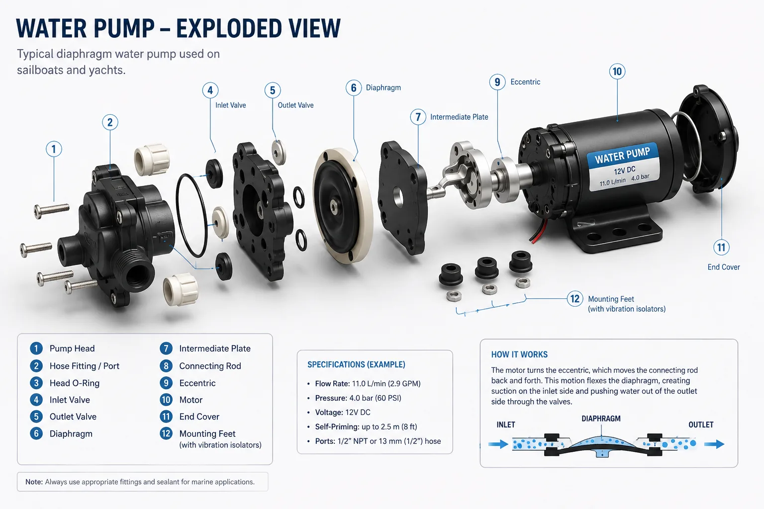
Motor & eccentric
The electric motor rotates an eccentric drive that converts rotary motion into repeated diaphragm movement.
Diaphragm & valves
The flexible diaphragm changes chamber volume while one-way inlet and outlet valves control the direction of water flow.
Pressure switch
On conventional pumps, the pressure switch controls automatic start and stop based on system pressure.
Interactive system explorer
source
valve
filter
12/24 V
Pressure & accumulator simulator
Fault simulator
Troubleshooting wizard
Diagnostic challenge
Pressure-loss simulator
Symptom → cause → first checks
| Symptom | Possible causes | Logical first checks |
|---|---|---|
| Pump silent | Switch, breaker/fuse, wiring, low voltage, pressure switch, motor | Create demand, then check power path and voltage according to pump/vessel documentation. |
| Runs but no water | Empty tank, selector closed, air leak, clogged strainer, lost prime | Tank → selector → strainer → suction hose/fittings → priming procedure. |
| Never stops | Open tap, leak, air ingestion, cannot reach cut-out pressure, switch issue | Close consumers, inspect for water loss, verify water supply and pressure build-up. |
| Rapid cycling | Accumulator issue, tiny demand, leak, pressure instability | Inspect accumulator and follow its correct depressurized pre-charge procedure. |
| Low pressure | Restriction, low voltage, air leak, worn pump, high simultaneous demand | Strainer, suction integrity, voltage under load, single-fixture flow. |
| Sputtering | Air after refill/tank switch, suction leak, empty tank | Tank level and selector, then suction fittings and strainer seal. |
| Pressure falls taps closed | Leak, check-valve backflow, relief discharge | Look for water and isolate branches methodically if the system allows it. |
Leak isolation trainer
The hidden training leak is in one branch. Isolate branches until pressure holds.
Emergency checklist
Knowledge quiz
Continue reading
Build your Croatia sailing knowledge with related TwoBoat guides, software, guides and planning tools.