
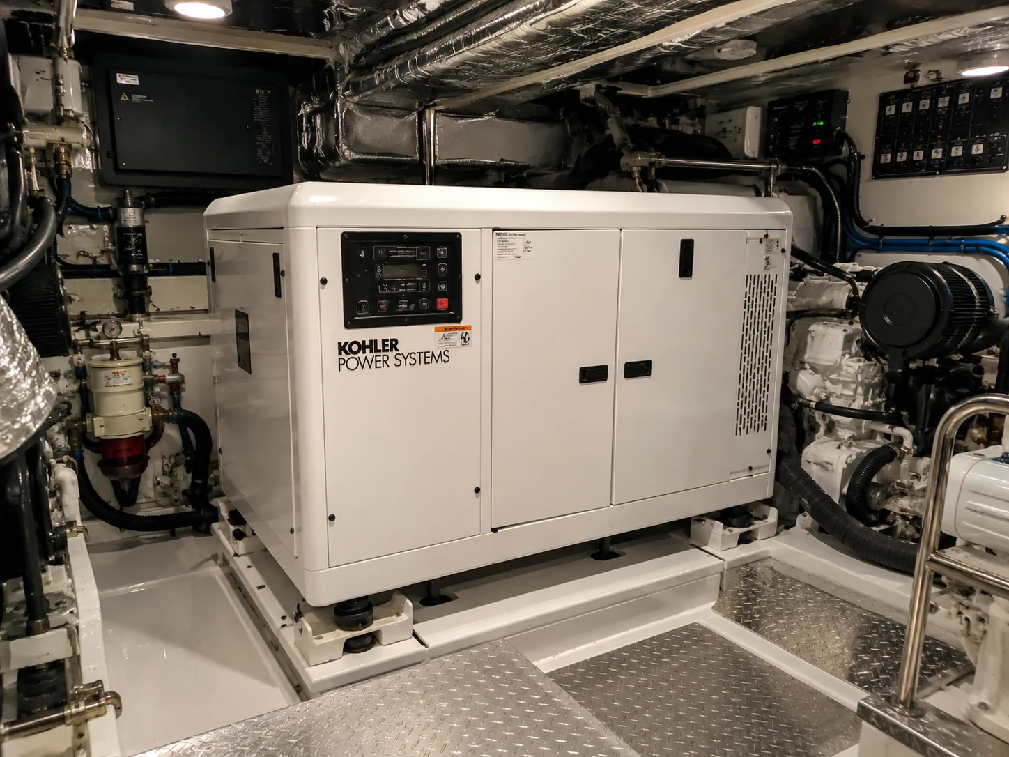
Marine Diesel Generator Maintenance, Common Problems, Diagnosis and Repair
A complete practical guide to operating, maintaining and troubleshooting compact marine diesel generators that produce nominal 220–240 V AC, usually at 50 Hz, aboard yachts, catamarans and sailing vessels. It covers the diesel engine, raw-water and closed-coolant circuits, fuel and lubrication systems, starting battery, charging alternator, synchronous AC alternator, automatic voltage regulator, governor, protection circuits, common symptoms, confirmation tests, repair procedures, diagnostic tools and replacement parts.
How a marine diesel generator works
The diesel engine converts fuel energy into steady mechanical rotation. A governor controls engine speed because alternator frequency depends directly on rotational speed and pole count. A four-pole alternator normally produces 50 Hz at approximately 1500 rpm, while a two-pole alternator normally produces 50 Hz at approximately 3000 rpm. The alternator rotor creates a magnetic field and the stator produces AC power. An automatic voltage regulator, or AVR, adjusts excitation to maintain voltage as load changes.
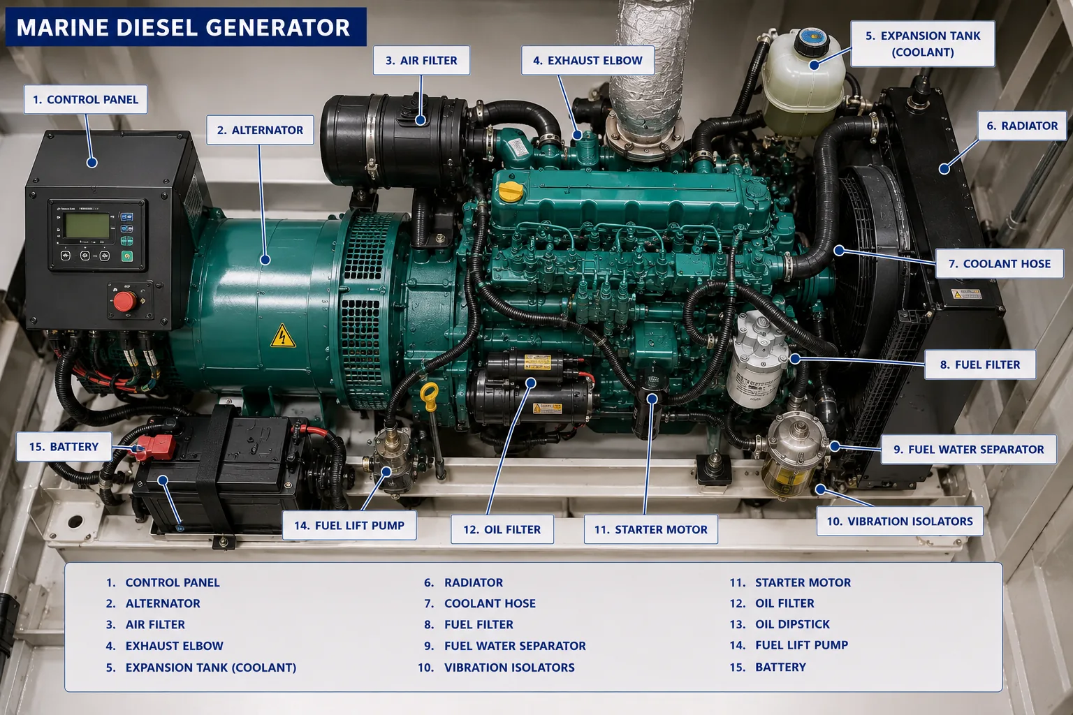
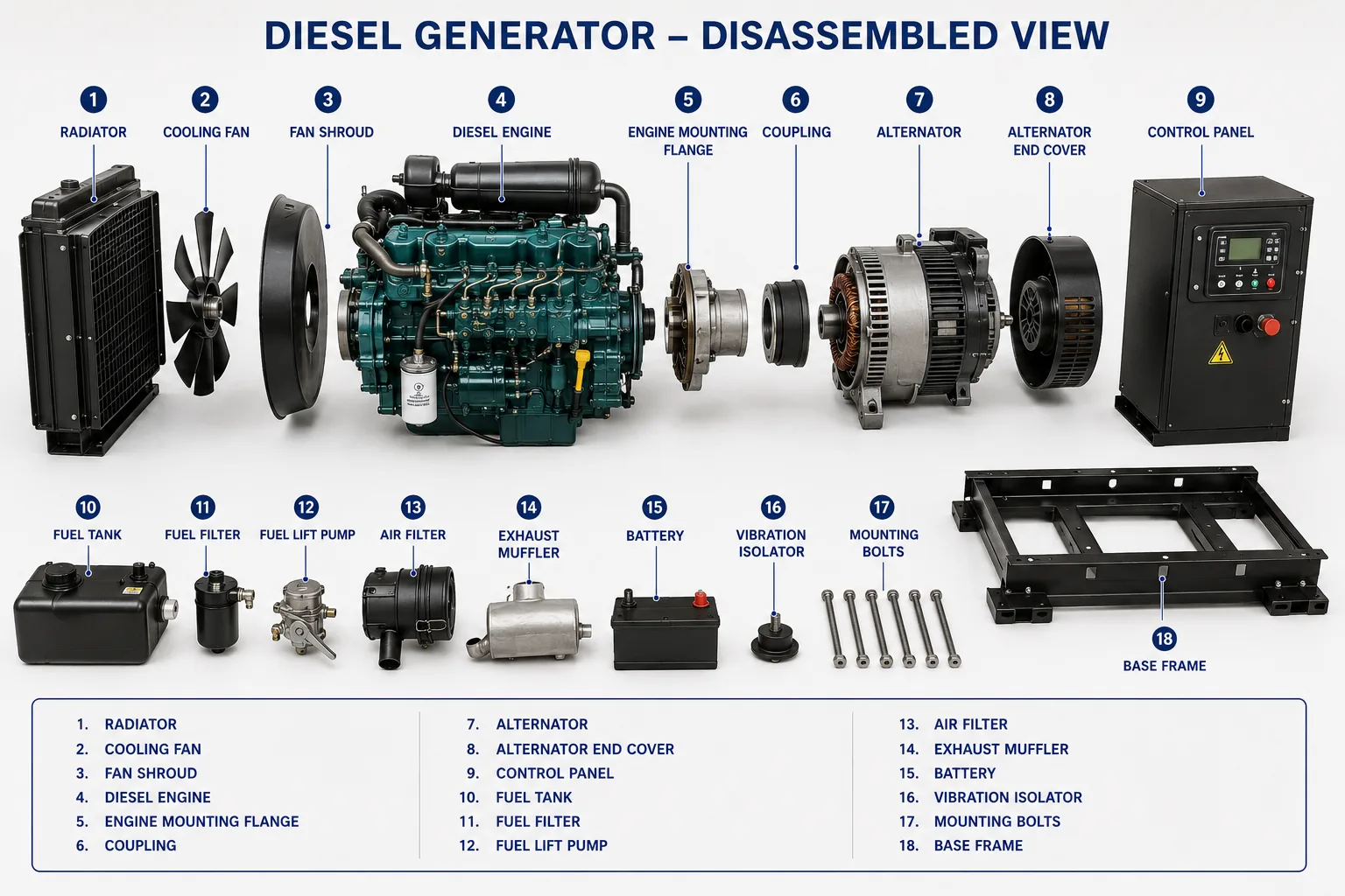
The generator also depends on a starting battery, starter motor, charging alternator, fuel lift and injection equipment, lubricating-oil system, raw-water pump, heat exchanger, wet exhaust, control panel, temperature/oil/speed sensors, output breaker and a safe changeover arrangement that prevents shore power, inverter and generator from being connected incorrectly.
Interactive generator symptom finder
Search for observations such as cranks but will not start, no 230 V output, 47 Hz, 260 V, overheating, black smoke, breaker trips or battery not charging.
Fast triage: what should you check first?
| Symptom | First safe checks | Stop immediately when |
|---|---|---|
| No crank | Starting battery, isolator, fuse, emergency stop, relay and voltage drop. | Cables smoke, battery swells, starter locks or engine cannot rotate. |
| Cranks but does not start | Fuel valve, separator, filters, bleeding, stop solenoid, preheat and cranking speed. | Raw water accumulates during repeated cranking, fuel leaks or hydrolock is suspected. |
| No AC output | Engine rpm/frequency, breaker, transfer switch, AVR supply/sensing and excitation. | Exposed live parts, burning, arcing or unknown backfeed exists. |
| Low/high voltage | Measure voltage and frequency together at no load and under controlled load. | Voltage is outside equipment limits or rises uncontrollably. |
| Wrong frequency | Verify rpm, governor response, load and fuel supply. | Overspeed occurs or frequency continues rising. |
| Overheating | Seacock, strainer, seawater discharge, impeller, coolant and load. | No cooling-water flow, coolant boils or exhaust components overheat. |
| Breaker/RCD trip | Disconnect branch loads, inspect for water/shorts and test one circuit at a time. | Repeated tripping, burning smell or insulation damage is present. |
Preventive maintenance and routine inspection
Before every start
- Ventilate the engine space and check for fuel, oil, coolant and seawater leaks.
- Confirm the raw-water seacock is open and the strainer is clean and sealed.
- Check engine-oil and coolant levels using the model procedure.
- Inspect belts, hoses, exhaust connections and the starting battery.
- Ensure the generator breaker and large AC loads are off before starting.
Immediately after start
- Confirm oil pressure and charging voltage.
- Verify a healthy pulse of cooling water at the wet exhaust.
- Listen for knocking, belt squeal, bearing noise or exhaust leaks.
- Allow the engine to stabilize, then verify approximately rated voltage and frequency before closing the breaker.
- Add loads gradually and monitor current, voltage, frequency, smoke and temperature.
Routine service
- Change engine oil and filter at the manufacturer interval and at least seasonally where required.
- Drain the water separator and replace fuel filters before restriction causes speed instability.
- Inspect/replace the raw-water impeller and locate every missing blade fragment.
- Inspect heat exchanger, exhaust mixing elbow, belts, mounts, hoses and anodes where fitted.
- Exercise the generator under meaningful load; prolonged very light loading promotes carbon buildup and wet stacking.
- Record hours, voltage, frequency, current, temperatures, alarms and parts used.
Recommended maintenance schedule
| Interval | Tasks | Record |
|---|---|---|
| Before each use | Leaks, oil, coolant, seacock, strainer, belts, battery, exhaust-water flow, voltage and frequency. | Hours, alarms and unusual observations. |
| Weekly / active charter use | Drain separator, inspect terminals, hoses, mounts and load behavior. | Battery voltage, frequency and peak load. |
| 50–100 hours or model interval | Oil/filter service, fuel-system inspection, belt and impeller inspection. | Oil type, filter part numbers and impeller condition. |
| 250–500 hours | Fuel/air filters, valve clearance where specified, cooling inspection, electrical torque checks. | Valve readings, voltage drop and insulation observations. |
| Annually | Coolant quality, heat exchanger/exhaust elbow, battery load test, full-load test and protection test. | No-load/full-load voltage, frequency, current and temperatures. |
| Major service | Injectors, compression, mounts, alternator bearings/windings, AVR/governor performance. | Test reports and replaced components. |
Essential diagnostic tools and onboard spare parts
Core tools
- CAT-rated true-RMS multimeter and non-contact voltage indicator.
- AC/DC clamp meter with inrush capture.
- Frequency meter or laser tachometer.
- Battery tester and mechanical oil-pressure gauge.
- Infrared thermometer, torque wrench, filter wrench and impeller puller.
- Wiring diagram, service manual, lockout/tagout equipment and insulated tools.
Professional tools
- Insulation-resistance tester and low-resistance ohmmeter.
- Oscilloscope and power-quality analyzer.
- Load bank.
- Fuel vacuum/pressure gauges, compression tester and injector equipment.
- Cooling-system pressure tester, thermal camera and exhaust backpressure gauge.
- Manufacturer engine/controller diagnostic interface.
Useful onboard spares
- Oil, oil filter, primary and secondary fuel filters.
- Raw-water impeller kit, pump gasket, strainer seal and hose clamps.
- Correct coolant, belts, fuses, relays and approved sensors.
- Fuel hose, coolant hose, electrical terminals and heat-shrink.
- Model-specific AVR or stop solenoid only where carrying one is practical.
Never improvise
- Do not install a larger breaker or fuse.
- Do not bypass oil-pressure, temperature or overspeed protection.
- Do not adjust sealed governor or injection-pump screws without data.
- Do not flash an alternator field using an improvised method.
- Do not megger connected electronic controllers or AVRs unless the manual permits it.
1. Generator Will Not Crank
Symptoms
- The start command produces no engine rotation.
- The control panel may be dark, reset, or show a low-battery or start-failure alarm.
- A relay may click once, chatter repeatedly, or remain silent.
- Cabin lights may dim sharply when START is pressed.
Most likely causes
- Discharged or failed starting battery.
- Loose, corroded or overheated battery cables and grounds.
- Open battery isolator, fuse, breaker or emergency-stop circuit.
- Failed starter relay, starter solenoid or starter motor.
- Control-panel, interlock, neutral/remote-start or shutdown circuit fault.
- Engine mechanically seized or hydrolocked.
How to confirm the fault
- Open the generator output breaker and isolate shore power/inverter backfeed before working.
- Measure battery voltage directly at the posts. Then measure again while START is pressed; a severe collapse indicates a weak battery, excessive resistance or a locked starter/engine.
- Perform voltage-drop tests from battery positive to starter positive and from starter housing to battery negative while cranking is attempted.
- Confirm start-enable voltage reaches the starter relay and solenoid. A click with no motor rotation requires high-current testing; no click requires control-circuit testing.
- Inspect the flywheel or crankshaft for permitted manual rotation only after disabling fuel and start circuits. Stop if liquid is expelled from a cylinder or the engine cannot turn.
- Check controller fault history, emergency stop, oil-pressure bypass during cranking and all model-specific interlocks.
Repair procedure
- Charge and load-test the battery; replace it if capacity or internal resistance is unacceptable.
- Clean or replace damaged lugs, cables, isolators and grounds, then tighten to specified torque.
- Replace a confirmed failed fuse, relay, solenoid or starter motor only after correcting the cause.
- Repair control wiring, connectors or interlocks and protect them from moisture and vibration.
- If the engine is seized or hydrolocked, do not force the starter. Correct the mechanical or water-ingress cause and inspect for internal damage.
- Retest cranking speed, battery voltage and cable temperature before allowing the engine to start.
Basic tools
- True-RMS multimeter
- Insulated hand tools
- Battery terminal brush
- Wiring diagram
- Flashlight
Professional diagnostic equipment
- Battery conductance/load tester
- DC clamp meter with inrush capture
- Milliohm meter
- Starter bench tester
- Manufacturer diagnostic interface
2. Engine Cranks but Does Not Start
Symptoms
- The starter turns the engine normally but combustion does not begin.
- White exhaust haze may appear during cranking, or there may be no smoke at all.
- The engine may try to fire only while the preheat button is held.
- The fault may follow a fuel-filter change, empty tank or long storage period.
Most likely causes
- Fuel shutoff valve closed, empty tank or blocked pickup.
- Air in the fuel system, clogged primary/secondary filter or water contamination.
- Failed electric lift pump, stop solenoid or injection-pump supply.
- Cold-start/glow-plug circuit failure.
- Low cranking speed, poor compression or incorrect valve clearance.
- Injector, injection-pump timing or ECU/sensor fault on electronically controlled units.
How to confirm the fault
- Confirm fuel level, tank valve position and that the correct fuel reaches the separator.
- Inspect the separator bowl for water, sludge, microbial growth and air bubbles. Replace restricted filters before deeper testing.
- Operate the lift pump and bleed the system exactly as the manufacturer specifies. Never loosen high-pressure common-rail lines.
- Verify stop-solenoid movement and supply voltage during START/RUN.
- Measure glow-plug current or resistance using model data; confirm preheat duration and relay output.
- Check cranking rpm, then perform compression or relative-compression testing if fuel delivery and preheat are correct.
- On electronic units, read fault codes and verify crank-speed, coolant-temperature and rail-pressure signals.
Repair procedure
- Drain contaminated fuel safely, clean the separator and replace primary and secondary filters.
- Repair suction leaks, cracked hoses, loose fittings or failed lift pump, then bleed until bubble-free fuel is obtained.
- Repair or replace the stop solenoid, preheat relay or glow plugs as confirmed.
- Adjust valve clearance and correct compression problems before replacing injection components.
- Service injectors or injection pump using a qualified diesel workshop when delivery/timing is incorrect.
- After starting, inspect for leaks, confirm smooth warm-up and load-test progressively.
Basic tools
- Multimeter
- Filter wrench
- Bleeding hose and container
- Correct replacement filters
- Hand primer tools
Professional diagnostic equipment
- Low-pressure fuel gauge/vacuum gauge
- Glow-plug current clamp
- Compression tester
- Injector pop tester or common-rail diagnostics
- Manufacturer scan tool
3. Generator Starts, Then Stalls or Hunts
Symptoms
- The engine starts and stops within seconds or minutes.
- Engine speed repeatedly rises and falls.
- The unit may run with no load but stall as soon as a load is applied.
- A shutdown alarm may indicate low oil pressure, high temperature, overspeed or underspeed.
Most likely causes
- Air leak or restriction on the fuel-suction side.
- Blocked tank vent, pickup tube, filters or anti-siphon valve.
- Weak lift pump, contaminated fuel or water in the separator.
- Governor linkage, actuator or speed-control fault.
- Incorrect shutdown-sensor signal or wiring fault.
- Sudden overload, short circuit or alternator fault loading the engine.
How to confirm the fault
- Run only long enough to observe the exact alarm and whether stalling is mechanical or commanded by the controller.
- Temporarily test tank venting using the approved method and observe separator vacuum or fuel-pressure behavior.
- Inspect clear diagnostic lines, where permitted, for bubbles; pressure-test the suction side at low pressure.
- Compare engine speed and frequency before stalling. A falling frequency indicates loss of engine power; a stable engine with electrical trip points elsewhere.
- Disconnect all AC loads and retest. Then add loads one at a time while recording current, voltage and frequency.
- Check governor linkage for free movement and use diagnostic data to evaluate actuator command versus actual speed.
Repair procedure
- Replace clogged filters and repair suction leaks, tank venting or pickup restrictions.
- Drain water/contamination and clean the fuel system as required.
- Replace a weak lift pump or failed actuator only after confirming supply and control signals.
- Lubricate or adjust mechanical governor linkage strictly to the service manual; do not alter sealed speed settings casually.
- Replace defective shutdown sensors or repair their wiring after verifying the engine condition is genuinely safe.
- Correct overloads, short circuits or alternator faults before returning the generator to service.
Basic tools
- Multimeter
- Fuel filters
- Clear bleeding hose where approved
- Tachometer/frequency display
- Clamp meter
Professional diagnostic equipment
- Fuel vacuum/pressure gauge
- Oscilloscope/data logger
- Electronic engine scan tool
- Load bank
- Governor actuator test equipment
4. Engine Runs but There Is No 230 V AC Output
Symptoms
- The diesel engine reaches normal speed but the panel shows zero or near-zero AC voltage.
- The generator output breaker may remain closed yet onboard circuits are dead.
- Voltage may appear briefly and collapse.
- The frequency display may work while voltage does not, or both may read zero depending on sensor arrangement.
Most likely causes
- Generator output breaker, contactor, transfer switch or wiring is open.
- AVR has lost supply, sensing or excitation output.
- Loss of residual magnetism.
- Open rotor field, failed brushes/slip rings or rotating rectifier fault.
- Open stator winding, broken neutral or terminal connection.
- Controller inhibits output because speed, frequency or protection limits are not satisfied.
How to confirm the fault
- Isolate shore power, inverter and all sources. Prove the meter on a known source, then verify absence of voltage at the generator terminals using rated PPE and procedures.
- Check voltage at alternator output before and after the generator breaker/contactor. This separates alternator generation from distribution failure.
- Verify engine speed and frequency pickup. Most 50 Hz sets operate at approximately 1500 rpm for four-pole alternators or 3000 rpm for two-pole alternators.
- Inspect AVR supply and sensing fuses, plugs and terminals. Compare AVR input, sensing and field output with the exact wiring diagram.
- Measure rotor-field and stator-winding resistance only with the AVR/electronics safely disconnected as specified. Check for open circuit, shorted turns indicators and ground faults.
- Inspect brushes, slip rings or rotating diodes on applicable designs. Do not flash the field unless the manufacturer provides an exact procedure.
Repair procedure
- Repair the breaker, contactor, transfer switch or output wiring when alternator voltage is present upstream.
- Replace blown sensing/excitation fuses only after locating the cause.
- Repair loose terminals, damaged brush gear, slip rings, field wiring or rotating rectifiers.
- Replace or correctly configure a confirmed failed AVR; verify voltage setting and frequency/under-speed protection.
- Rewind or replace a damaged rotor/stator through a qualified alternator workshop.
- Apply load gradually and confirm voltage, frequency, current balance, temperature and breaker operation.
Basic tools
- CAT-rated true-RMS multimeter
- Lockout/tagout equipment
- Insulated tools
- Wiring diagram
- Frequency meter
Professional diagnostic equipment
- Insulation-resistance tester
- Low-resistance ohmmeter
- Oscilloscope
- AVR/field test setup
- Load bank and power-quality analyzer
5. Output Voltage Is Too Low
Symptoms
- Output remains below the specified range, for example 180–215 V on a nominal 230 V system.
- Lights are dim, motors struggle to start and chargers may alarm.
- Voltage may be correct with no load but fall excessively under load.
- Frequency may be low at the same time.
Most likely causes
- Engine speed/frequency below specification.
- Generator overloaded or a connected appliance has excessive starting current.
- AVR setting, sensing circuit or excitation supply fault.
- High resistance at breaker, contactor, neutral or output terminals.
- Weak residual magnetism, brush/slip-ring or rotating-diode problem.
- Shorted stator/rotor winding or engine unable to produce rated power.
How to confirm the fault
- Measure voltage and frequency simultaneously at no load and at several controlled load steps.
- If voltage and frequency both fall, diagnose engine speed, fuel supply, governor and overload before adjusting the AVR.
- If frequency remains correct but voltage is low, inspect AVR sensing, excitation output and alternator connections.
- Measure voltage drop across the generator breaker, contactor and transfer switch under load. Any significant drop requires repair.
- Compare each line-to-neutral and line-to-line reading for the configured alternator; investigate imbalance or a loose neutral.
- Use load-bank testing to determine whether the problem begins at a specific percentage of rated kW/kVA.
Repair procedure
- Restore rated engine speed and power by correcting fuel, air, exhaust, cooling or governor problems.
- Remove overloads and sequence large motor/compressor loads.
- Repair high-resistance terminals, breaker contacts, neutral links or transfer equipment.
- Correct AVR sensing/configuration and set voltage only using the approved procedure and calibrated meter.
- Repair excitation components or damaged windings as confirmed.
- Verify stable voltage during load steps and confirm connected equipment operates normally.
Basic tools
- True-RMS multimeter
- Clamp meter
- Frequency meter
- Infrared thermometer
- Torque tools
Professional diagnostic equipment
- Power-quality analyzer
- Load bank
- Oscilloscope
- Insulation tester
- AVR/alternator test equipment
6. Output Voltage Is Too High
Symptoms
- Voltage exceeds the generator’s specified range.
- Chargers, inverters, air-conditioning controls or appliances trip on overvoltage.
- Lamps are unusually bright and may fail.
- Voltage may jump high suddenly after vibration or maintenance.
Most likely causes
- AVR sensing lead open, loose or connected incorrectly.
- Failed AVR power stage or incorrect voltage adjustment.
- Engine overspeed/high frequency.
- Wrong alternator reconnection, jumper or controller configuration.
- Neutral fault causing abnormal line-to-neutral voltages.
- Incompatible replacement AVR or incorrect droop/remote-trim wiring.
How to confirm the fault
- Open the generator breaker immediately and protect onboard equipment.
- Measure frequency and voltage directly at the generator terminals with a calibrated true-RMS meter.
- If frequency is high, correct speed/governor first. Do not use AVR adjustment to hide overspeed.
- Inspect AVR sensing wires and fuses from the alternator terminals to the AVR. An open sense circuit can drive excitation high.
- Confirm alternator link configuration and neutral integrity against the exact schematic.
- Disconnect remote voltage trim or parallel/droop accessories only according to the manual and test the base AVR circuit.
Repair procedure
- Repair sensing wiring, connectors, fuses and neutral links.
- Correct governor/actuator faults and set no-load and full-load frequency as specified.
- Install the correct AVR and configure frequency, stability and voltage settings using the manufacturer procedure.
- Correct alternator reconnection links and controller voltage scaling.
- Inspect connected equipment for damage before re-energizing.
- Load-test progressively and verify overvoltage protection operation.
Basic tools
- True-RMS multimeter
- Frequency meter
- Insulated tools
- Wiring diagram
- Lockout kit
Professional diagnostic equipment
- Power-quality analyzer
- Oscilloscope
- AVR test bench
- Load bank
- Manufacturer configuration software
7. Frequency Is Below 50 Hz
Symptoms
- Frequency is below the specified 50 Hz range.
- Induction motors run slowly, draw high current or overheat.
- Voltage may also sag and the engine note sounds slow.
- Frequency drops sharply when air conditioning, watermaker or charger load is applied.
Most likely causes
- Engine rpm is too low due to governor setting or actuator fault.
- Generator overloaded or a large load has poor power factor/starting current.
- Fuel restriction, dirty air filter, exhaust restriction or weak compression limits engine power.
- Governor linkage sticks or electronic speed control is unstable.
- Incorrect frequency configuration or speed-sensor calibration.
- Propulsion-style idle setting used instead of fixed generator speed on converted installations.
How to confirm the fault
- Confirm frequency with an independent meter and verify rpm with a laser tachometer. For synchronous alternators, frequency is directly related to rpm and pole count.
- Measure no-load frequency, then add load in controlled steps while recording kW/kVA, current and exhaust smoke.
- If no-load frequency is low, inspect speed setpoint, linkage, actuator and speed sensor.
- If only full-load frequency is low, test fuel supply, filters, air intake, exhaust backpressure and engine power.
- Check for one appliance drawing abnormal current or a compressor that fails to accelerate.
- Do not raise speed beyond the model specification to compensate for an overload or engine fault.
Repair procedure
- Restore fuel and air supply, service filters and correct exhaust restriction.
- Repair or calibrate governor linkage, actuator, speed sensor or electronic controller.
- Reduce or sequence loads and repair appliances with excessive current draw.
- Adjust frequency at no load and rated load using the exact service procedure.
- Verify voltage after speed correction because AVR behavior may change.
- Record final no-load and full-load frequency and rpm.
Basic tools
- Frequency meter
- Laser tachometer
- Clamp meter
- Fuel-filter tools
- Service manual
Professional diagnostic equipment
- Load bank
- Power analyzer
- Fuel vacuum/pressure gauge
- Exhaust backpressure gauge
- Governor diagnostic software
8. Frequency Is Above 50 Hz or Overspeed Occurs
Symptoms
- Frequency is consistently high or rises uncontrollably.
- The controller trips on overspeed.
- Voltage may also rise.
- Engine speed may surge after starting or after load removal.
Most likely causes
- Governor setpoint too high or linkage stuck.
- Electronic actuator driven to excess fuel by controller/sensor fault.
- Speed sensor signal intermittent or incorrectly calibrated.
- Load suddenly removed and governor cannot recover correctly.
- Injection-pump/governor internal failure.
- Incorrect 50/60 Hz configuration.
How to confirm the fault
- Open the output breaker and stop the engine if speed exceeds limits or continues rising.
- Verify actual rpm independently; do not rely only on a faulty panel display.
- Inspect linkage and actuator for free return to minimum-fuel position.
- Check speed-sensor gap, wiring, shielding and signal quality.
- Verify controller 50 Hz configuration, rated rpm and overspeed threshold.
- If mechanical governor behavior is abnormal, remove the pump/governor for specialist testing rather than adjusting sealed screws.
Repair procedure
- Free or replace damaged linkage and return springs.
- Repair speed-sensor wiring or replace/calibrate the sensor.
- Replace or configure the actuator/controller as confirmed.
- Service the mechanical governor or injection pump through an authorized diesel shop.
- Correct 50/60 Hz settings and verify load-rejection response.
- Test overspeed shutdown and ensure fuel is positively cut off.
Basic tools
- Frequency meter
- Laser tachometer
- Inspection tools
- Multimeter
- Service manual
Professional diagnostic equipment
- Oscilloscope
- Governor controller software
- Actuator current tester
- Load bank for load-rejection test
- Injection-pump test bench
9. Frequency and Engine Speed Hunt or Oscillate
Symptoms
- Frequency repeatedly moves above and below 50 Hz.
- The engine note surges rhythmically.
- Voltage may fluctuate with the speed.
- The problem may occur only at light load or when a compressor cycles.
Most likely causes
- Air in fuel, restricted supply or weak lift pump.
- Governor gain/stability setting incorrect.
- Sticky linkage, worn actuator or speed-sensor noise.
- Unstable or rapidly cycling AC load.
- Cylinder misfire, injector imbalance or poor compression.
- AVR/load interaction on small sets with nonlinear chargers or inverters.
How to confirm the fault
- Observe whether rpm and frequency oscillate together. If voltage alone oscillates, diagnose the AVR instead.
- Run with all AC loads disconnected. Add resistive load, then individual electronic/motor loads to identify interaction.
- Inspect fuel for bubbles and measure suction vacuum/pressure.
- Check actuator linkage for friction and backlash; view commanded versus actual speed where diagnostics permit.
- Use an oscilloscope or data logger to inspect speed-sensor signal and actuator drive.
- Check exhaust temperature by cylinder and perform injector/compression tests if one cylinder contributes unevenly.
Repair procedure
- Repair fuel leaks/restrictions and replace filters or lift pump.
- Clean and lubricate linkage only where specified; replace worn joints or actuator.
- Tune governor gain/stability strictly according to the service manual under controlled load.
- Repair the cycling or defective appliance and improve load sequencing.
- Service injectors, valves or compression defects.
- For difficult AVR/governor interaction, use the approved regulator settings or manufacturer support.
Basic tools
- Frequency meter
- Clamp meter
- Fuel filters
- Infrared thermometer
- Inspection tools
Professional diagnostic equipment
- Data logger/oscilloscope
- Power-quality analyzer
- Fuel vacuum gauge
- Cylinder temperature probes
- Governor diagnostic interface
10. Generator Overheats or Shuts Down on High Temperature
Symptoms
- Coolant-temperature alarm or automatic shutdown occurs.
- Little or no seawater exits with the exhaust.
- The coolant tank boils, hoses harden or the engine room becomes unusually hot.
- Temperature rises only under heavy load or after several minutes.
Most likely causes
- Seacock closed, intake blocked or strainer clogged/leaking air.
- Raw-water impeller damaged, pump cover worn or belt slipping.
- Heat exchanger, oil cooler or exhaust mixing elbow restricted.
- Low coolant, air lock, coolant leak or incorrect mixture.
- Thermostat stuck, circulation pump failed or radiator/ventilation problem on air-cooled variants.
- Generator overloaded, injection timing incorrect or exhaust backpressure excessive.
How to confirm the fault
- Stop the generator promptly; do not remove a hot pressure cap.
- Check seawater discharge immediately after restart only if safe. If absent, stop and inspect seacock, strainer, hoses and impeller.
- Inspect every recovered impeller blade. Missing fragments must be located downstream, commonly at cooler or exchanger inlets.
- When cool, pressure-test the closed coolant circuit and verify coolant level/concentration.
- Measure temperatures across thermostat, heat exchanger, exhaust elbow and coolant hoses with an infrared thermometer or thermal camera.
- Test under increasing load while monitoring coolant temperature, raw-water flow and exhaust backpressure.
Repair procedure
- Open/clear the intake, reseal the strainer and replace collapsed hoses.
- Replace impeller, gasket and worn pump cover/cam; retrieve all blade fragments.
- Clean or professionally descale heat exchangers and replace a restricted exhaust elbow.
- Repair coolant leaks, replace thermostat or circulation pump and bleed air exactly as specified.
- Correct ventilation and overload conditions.
- After repair, run to full operating temperature and rated load while checking for leaks and stable temperature.
Basic tools
- Impeller puller
- Screwdrivers/socket set
- Infrared thermometer
- Coolant hydrometer/refractometer
- Drain containers
Professional diagnostic equipment
- Cooling-system pressure tester
- Raw-water flow meter
- Thermal camera
- Exhaust backpressure gauge
- Load bank
11. Low Oil Pressure Alarm or Shutdown
Symptoms
- Oil-pressure warning appears after start or during operation.
- The engine stops automatically.
- Mechanical noise, ticking or knocking may be present.
- Alarm may occur only when hot or at idle/no load.
Most likely causes
- Oil level low, wrong viscosity, fuel dilution or coolant contamination.
- Defective pressure switch/sender or wiring.
- Restricted, incorrect or collapsed oil filter.
- Worn oil pump, relief valve or excessive bearing clearance.
- Oil pickup blockage or air leak.
- Engine operated at incorrect inclination or severe vessel motion exposing pickup.
How to confirm the fault
- Stop immediately if pressure is genuinely low or mechanical noise is present.
- Check oil level and condition on a level vessel after the specified drain-back time.
- Inspect for external leaks and signs of diesel fuel, coolant or metal in the oil.
- Install a calibrated mechanical pressure gauge at the specified test port and compare cold/hot readings at rated speed.
- If mechanical pressure is normal, test sender/switch resistance, supply and wiring.
- If pressure is low, inspect filter, pickup, relief valve, pump and bearing clearances before further running.
Repair procedure
- Correct oil level and use only the specified oil grade and filter.
- Repair leaks and replace a faulty sender/switch or wiring.
- Investigate fuel dilution, coolant entry or metal contamination; changing oil alone is not sufficient.
- Repair pickup, relief valve or oil pump faults.
- Overhaul the engine when bearing clearance or internal wear causes pressure loss.
- Prime the lubrication system as required and verify pressure before applying load.
Basic tools
- Correct oil and filter
- Mechanical pressure gauge adapter
- Multimeter
- Oil drain tools
- Inspection light
Professional diagnostic equipment
- Laboratory oil analysis
- Borescope
- Bearing-clearance tools
- Oil-pump test equipment
- Engine diagnostic interface
12. White, Black or Blue Exhaust Smoke
Symptoms
- White smoke or vapor persists after warm-up.
- Black smoke appears under load or during acceleration.
- Blue-gray smoke has an oily smell and oil consumption rises.
- Soot or oily residue collects at the exhaust outlet.
Most likely causes
- White: cold combustion, failed glow plug, low compression, injector dribble, water/coolant entry.
- Black: overload, restricted air intake/exhaust, poor injector spray, excess fueling or low rpm.
- Blue: engine oil entering cylinders through rings, valve guides, turbo seals or overfilled crankcase.
- Wet exhaust steam from inadequate seawater mixing can be mistaken for white combustion smoke.
- Exhaust mixing elbow restriction increases backpressure and smoke.
- Long light-load operation causes carbon buildup and wet stacking.
How to confirm the fault
- Identify color, smell, temperature and whether smoke changes after warm-up or load change.
- Confirm correct frequency/rpm and actual electrical load before blaming injectors.
- Inspect air filter, intake, crankcase breather and exhaust mixing elbow.
- Compare exhaust-manifold temperature by cylinder to locate a weak or overfueling cylinder.
- Check coolant and oil consumption, then perform compression/leak-down and injector testing as needed.
- Inspect for seawater flow and distinguish normal steam from unburned-fuel smoke.
Repair procedure
- Service air intake, exhaust elbow and fuel filters.
- Repair overload or low-speed operation and periodically operate at a healthy load within manufacturer guidance.
- Test and service injectors; correct injection timing or pump faults.
- Repair glow-plug, compression, valve, piston-ring or turbocharger defects as confirmed.
- Correct oil level and crankcase ventilation.
- Investigate any coolant loss or water ingress immediately.
Basic tools
- Infrared thermometer
- Multimeter
- Air/fuel filters
- Inspection mirror
- Oil/coolant records
Professional diagnostic equipment
- Injector tester
- Compression/leak-down tester
- Borescope
- Exhaust backpressure gauge
- Emissions/smoke analyzer
13. Generator Breaker Trips or Earth-Leakage Protection Operates
Symptoms
- Main generator breaker opens immediately or after a delay.
- RCD/RCBO/earth-leakage alarm trips when generator power is selected.
- One appliance or circuit causes repeatable tripping.
- Cables, breaker or transfer equipment may become hot.
Most likely causes
- Total load exceeds generator or breaker rating.
- Short circuit, damaged appliance, wet cable or failed motor winding.
- Insulation leakage in alternator, distribution wiring or connected equipment.
- Incorrect neutral-earth bonding or transfer-switch arrangement.
- Loose/high-resistance breaker or terminal creating heat.
- Breaker/RCD is defective or incorrectly rated/configured.
How to confirm the fault
- Do not repeatedly reset a breaker into a fault. Disconnect all branch loads.
- Inspect for burning, water ingress and damaged insulation.
- Measure each branch current and reconnect circuits one at a time to isolate the fault.
- Perform insulation-resistance testing only with sensitive electronics disconnected and according to system design.
- Verify generator neutral-earth bonding and transfer switching against marine electrical standards and the vessel schematic.
- Use leakage-current clamp measurement to locate cumulative or single-circuit leakage.
Repair procedure
- Remove overload and implement load management.
- Repair the defective appliance, cable or connector and dry/replace water-damaged components.
- Correct neutral-earth bonding and transfer-switch wiring through a qualified marine electrician.
- Replace overheated terminals, breaker, RCD or contactor with correctly rated marine components.
- Repair alternator winding insulation or contamination as diagnosed.
- Complete functional, polarity, insulation and protection tests before returning power to the vessel.
Basic tools
- CAT-rated multimeter
- Clamp meter
- Lockout kit
- Insulated tools
- Circuit schedule
Professional diagnostic equipment
- Insulation-resistance tester
- Leakage-current clamp
- RCD tester
- Power analyzer
- Thermal camera
14. Starting Battery Does Not Charge or Overcharges
Symptoms
- Battery voltage does not rise after the generator starts.
- Repeated no-start occurs despite regular operation.
- Charging warning remains active.
- Battery voltage rises excessively, electrolyte smells, or the battery becomes hot.
Most likely causes
- Loose/broken charging-alternator belt.
- Failed alternator, regulator, rectifier or excitation circuit.
- Open fuse, isolator, diode splitter or charging relay.
- Corroded cable/ground causing voltage drop.
- Remote sense wire open, producing overcharge.
- Battery internally failed or incompatible charger/alternator settings.
How to confirm the fault
- Measure battery voltage at rest and during operation directly at the posts.
- Inspect belt condition/tension and alternator rotation.
- Measure voltage at alternator B+ and compare with battery voltage under charging load.
- Check excitation/indicator circuit, charging fuse and ground voltage drop.
- For overcharge, inspect regulator sense connection and compare alternator output with actual battery voltage.
- Load-test the battery and verify chemistry/settings for lead-acid, AGM, gel or lithium installations.
Repair procedure
- Adjust or replace the belt and align pulleys.
- Repair wiring, fuse, ground, charge relay or isolator.
- Replace or rebuild a confirmed failed alternator/regulator.
- Repair the remote-sense circuit and any overheated battery connections.
- Replace a failed battery and correct battery-management settings.
- Verify stable charging voltage and current through warm-up and load changes.
Basic tools
- Multimeter
- Belt-tension tools
- Battery terminal tools
- Service manual
- Infrared thermometer
Professional diagnostic equipment
- Battery analyzer
- DC clamp meter
- Alternator test bench
- Oscilloscope for diode ripple
- BMS diagnostic interface
15. Excessive Vibration, Knocking or Bearing Noise
Symptoms
- Generator vibration is stronger than normal or transmitted into the hull.
- Knocking, rattling, squealing or grinding changes with load.
- Exhaust hose, wiring or enclosure contacts nearby structures.
- Voltage/frequency may remain normal despite mechanical noise.
Most likely causes
- Collapsed or loose flexible engine mounts.
- Loose mounting base, enclosure, exhaust or heat shield.
- Cylinder misfire or injector imbalance.
- Alternator bearing, cooling pump, belt idler or starter damage.
- Coupling/alignment fault on remote-mounted alternators.
- Propeller-shaft vibration or vessel machinery incorrectly attributed to the generator.
How to confirm the fault
- Stop immediately for metallic knocking, grinding, smoke or sudden severe vibration.
- Inspect mounts, base, exhaust, hoses, guards and enclosure for witness marks and loose hardware.
- Use a mechanic’s stethoscope or vibration probe to localize bearings and accessories.
- Compare exhaust temperature by cylinder to detect misfire.
- Remove belts only according to the manual for brief accessory-isolation testing.
- Measure mount height/alignment and vibration at no load and rated load.
Repair procedure
- Replace mounts as a matched set when collapsed, oil-soaked or separated; align and torque correctly.
- Tighten/repair base, enclosure, exhaust supports and guards.
- Service injector, valve or compression faults causing uneven firing.
- Replace failed bearings, pumps, idlers or alternator components.
- Correct coupling alignment using the manufacturer procedure.
- Retest across the load range and verify hoses/cables have adequate clearance.
Basic tools
- Torque wrench
- Inspection light
- Mechanic stethoscope
- Infrared thermometer
- Straightedge/feeler gauges
Professional diagnostic equipment
- Vibration analyzer
- Laser alignment equipment
- Dial indicator
- Bearing tools
- Cylinder-balance diagnostics
Complete step-by-step diagnostic workflow
Make the system safe
Open the generator breaker, isolate shore power and inverter paths, disable automatic start and identify every energy source. Ventilate the compartment. Do not work alone on live AC equipment.
Record the exact symptom
Note whether the engine cranks, starts, reaches rated speed, produces exhaust-water flow and generates voltage. Record alarm codes, voltage, frequency, current, smoke color, temperature and the exact load connected.
Separate engine faults from alternator faults
If rpm/frequency are wrong, diagnose the diesel engine, fuel system and governor first. If rpm/frequency are correct but voltage is wrong, focus on AVR, excitation, windings and output connections.
Test no-load operation
With the breaker open, verify oil pressure, coolant temperature, charging voltage, seawater flow, engine speed, frequency and alternator voltage. Do not apply load until these are stable.
Apply controlled load
Add loads in steps, preferably using a load bank. Record voltage, frequency, current, power, smoke and temperature at each step. A problem that begins at a repeatable load level is highly diagnostic.
Measure voltage drops and temperatures
Measure across cables, grounds, breakers, contactors and transfer equipment while loaded. Use thermal imaging or an infrared thermometer to locate resistance, poor cooling and overloaded connections.
Repair only the confirmed cause
Avoid random AVR, governor or sensor adjustments. Replace parts only after verifying supply, ground, signal and mechanical condition. Record original settings before any adjustment.
Verify the complete system
After repair, perform cold start, warm-up, no-load, staged-load and shutdown tests. Confirm protection devices, transfer switching, charging, cooling, voltage, frequency and absence of leaks or overheating.
Safe starting procedure
- Ventilate the generator compartment and inspect for fuel, oil, coolant and exhaust leaks.
- Open the raw-water seacock and verify the strainer is clean and correctly sealed.
- Check engine oil, coolant and starting-battery condition.
- Ensure shore/generator/inverter changeover is safe, generator breaker is open and major loads are off.
- Preheat if required, then crank only for the specified maximum duration. Allow starter cooling between attempts.
- After start, confirm oil pressure, charging voltage and cooling-water discharge immediately.
- Warm up briefly at no load, then verify nominal voltage and approximately 50 Hz.
- Close the generator breaker and add large loads one at a time.
Safe shutdown procedure
- Switch off heavy loads such as air conditioning, water heaters, watermakers and large chargers.
- Open the generator breaker or transfer the vessel load using the approved system.
- Run unloaded for the model-specified cool-down period, especially after heavy loading.
- Stop using the normal control. Do not use emergency stop for routine shutdown.
- Inspect for leaks, smells, overheating and abnormal coolant level.
- Record hours, load, alarms and maintenance required.
- Close the seacock only when vessel procedures require it and ensure a clear reminder prevents starting with it closed.
Voltage and frequency reference
| Observation | Likely direction | Do not do |
|---|---|---|
| Low voltage + low frequency | Low rpm, overload or insufficient engine power. | Do not raise AVR voltage to hide low speed. |
| Low voltage + correct frequency | AVR sensing/excitation, voltage drop or winding issue. | Do not adjust governor first. |
| High voltage + high frequency | Overspeed/governor fault. | Do not correct solely with AVR adjustment. |
| High voltage + correct frequency | AVR or sensing/neutral fault. | Do not connect sensitive appliances. |
| Stable frequency + unstable voltage | AVR, excitation, brushes/diodes or load interaction. | Do not assume fuel fault. |
| Unstable frequency and voltage together | Governor, fuel supply, cylinder balance or unstable load. | Do not tune AVR before speed is stable. |
Frequency / rpm calculator
Frequently asked questions
Should a generator always produce exactly 230 V and 50.00 Hz?
The acceptable range is model- and equipment-specific. Measure with a calibrated true-RMS meter and compare no-load and full-load values with the generator manual. A small governed droop may be normal; large or unstable deviations are not.
Why should voltage and frequency be measured together?
Frequency follows engine speed, while voltage is mainly controlled by excitation and the AVR. The combination quickly separates an engine/governor problem from an alternator/regulator problem.
Can I adjust the AVR myself?
Only when you have the correct manual, calibrated instruments and understand voltage, stability, frequency protection and remote sensing. A wrong adjustment can damage onboard equipment or mask another fault.
Why does the generator need regular load?
Long operation at very light load can prevent complete combustion, promote carbon deposits and cause wet stacking. Apply a healthy, manufacturer-approved load regularly while monitoring temperature and exhaust condition.
When should a marine electrician be called?
Use a qualified technician for live AC work, insulation faults, neutral-earth bonding, transfer switching, repeated breaker/RCD trips, winding tests, AVR/field repairs and any situation where the system cannot be safely isolated.
Manage generator maintenance with TwoBoat
Record generator hours, recurring service intervals, inspections, faults, photographs, replacement parts, technician time and signed work orders using TwoBoat fleet maintenance and work-order management tools.
Continue reading
Build your Croatia sailing knowledge with related TwoBoat guides, software, guides and planning tools.